Device and method for correcting a spinal deformity

a technology for spinal deformities and devices, applied in the field of spinal deformities, can solve problems such as degeneration of discs, nerve or spinal cord damage, and inability to correct spinal deformities, and achieve the effects of less surrounding tissue damage or disruption, reducing discomfort and or deformities, and reducing pain and deformities

Active Publication Date: 2010-04-22
K2M +1
View PDF13 Cites 105 Cited by
  • Summary
  • Abstract
  • Description
  • Claims
  • Application Information

AI Technical Summary

Benefits of technology

[0021]One aspect of the present invention is directed to providing a device and method for alleviating discomfort and or deformity associated with the spinal column. Another aspect of the present invention is directed to providing a minimally invasive implant and method for alleviating discomfort associated with the spinal column. Another aspect of the present invention provides an anchoring device and method that requires less surrounding tissue damage or disruption. Another aspect of the present invention provides reinforcement of the spinous process for use in various spinal systems. Another aspect of the invention provides a minimally invasive, non-invasive, or remote adjustment or lengthening of an orthopedic device. Another aspect of the invention provides a minimally invasive, non-invasive, or remote adjustment, lengthening or shortening of a stabilization device. Another aspect of the present invention also provides an implant system and device suitable for minimally invasive, minimally disruptive and / or percutaneous posterior deployment across a plurality of motion segments and more than two motion segments. Different aspects of the invention may provide distraction forces to relieve pressure on certain structures, compression forces to fix or stabilize motion across structures, shock absorbing qualities to help relieve load from certain structures, and therapeutic activity to reduce inflammation and pain. Other aspects of the invention may supplement or bear load for degenerated, painful, or surgically removed joints, e.g., the facet joint. Another aspect of the invention may provide a method and system for treating deformities such as scoliosis. Other aspects of the invention may include sensors associated with implants or implanted at or near the bones, soft tissue, or joints of the spine and may provide feedback regarding the joint on an ongoing basis. The sensors may also be part of a feedback system that alters a property of an implant in response to sensing information. Another aspect of the invention may provide a device or method for delivering therapeutic substances at or near the spine.

Problems solved by technology

Certain spine conditions, defects, deformities (e.g., scoliosis) as well as injuries may lead to structural instabilities, nerve or spinal cord damage, pain or other manifestations.
For example, back pain is frequently caused by repetitive and / or high stress loads on or increased motion around certain boney or soft tissue structures.
The natural course of aging leads to degeneration of the disc, loss of disc height, and instability of the spine among other structural manifestations at or around the spine.
The facet joints may develop pain due to arthritic changes caused by increased loads.
Furthermore, osteophytes in the neural foramina and thickening of spinal ligaments can lead to spinal stenosis, or impingement of nerve roots in the spinal canal or neural foramina.
The typical techniques for fusion, distraction, decompression, and dynamic stabilization require open surgical procedures with removal of stabilizing muscles from the spinal column, leading to pain, blood loss, and prolonged recovery periods after surgery due in part to the disruption of associated body structures or tissue during the procedures.
Also, placing support structures between adjacent pedicle screws and across a joint requires accessing and working in an area from a difficult angle (the support structure is typically oriented somewhat perpendicular to an angle of access and through muscle and connective tissue).
Furthermore, these stabilization devices typically involve the use of 4 pedicle screws (each having a risk associated with it when placed in the spine), two on each side of a motion segment, and are not ideally suited for percutaneous stabilization required across more than one or two segments.
However, geometric placement of the device is difficult and the procedure is considered dangerous because the laminar screws could enter through anteriorly into the spinal canal and cause nerve damage.
Unintended consequences of fixation include stress shielding of bone, as well as transfer of load to adjacent, still dynamic motion segments, and eventual degeneration of adjacent motion segments.
However, this device has the disadvantage of requiring placement of 4 pedicle screws and associated tissue disruption.
Due to the risks, inconvenience, and recovery time required for surgical implantation of spinal devices, some patients may continue to prefer rigid fixation of a painful or degenerative motion segment over dynamic stabilization of the joint.
In addition, doctors may be reluctant to recommend dynamic stabilization for patients with back pain, because it may not alleviate pain to a patient's satisfaction.
Repeat spine procedures to remove one implant and replace it with another are associated with complications related to bleeding, surgical adhesions, destruction of bone, and other generic risks associated with surgical procedures.
The correction force in this device and in similar devices is a distraction force that may have several drawbacks including possible spinal cord damage, as well as the high loading on the upper and lower attachment sites.
This does not provide significant adjustment over time and requires fusion.
Once completed this does not provide an opportunity for delayed adjustment over time.
The spinous process contains thin walls of cortical bone, and thus, has been considered as not ideal for anchoring spinal implants as they may not support the implants under physiologic loads, or the intermittent high loads seen in traumatic situations.
Fixation has been attempted from spinous process to spinous process with poor results.
A disadvantage of this device is that it is not suitable for attaching to a pedicle screw and the depth and angle during deployment can be very difficult to track or visualize, thus increasing the possibility that the screw would extend into the spinal canal.

Method used


Image

  • Device and method for correcting a spinal deformity
  • Device and method for correcting a spinal deformity
  • Device and method for correcting a spinal deformity

Examples


Embodiment Construction

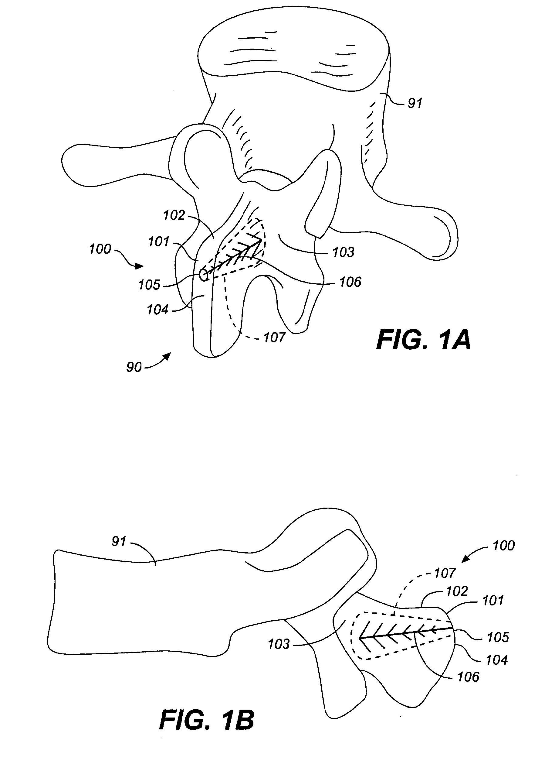
[0071]FIGS. 1A and 1B illustrate a reinforced posterior arch 100 of a first vertebra 91 of a spine 90, including a spinous process 101 and lamina 103. The first vertebra 100 of the spine 90 as illustrated includes a first spinous process 101 with a superior portion 102 having a posterior ridge 104 into which a hole 105 is drilled. The hole 105 may be drilled with a drill, a trocar, a large bore IV needle or similar sharp object through the external and relatively hard cortical bone, to reach the internal cancellous bone within the spinous process 101 and adjacent the lamina 103.

[0072]Once the cancellous bone is accessed, optionally, a tool such as a balloon tamp, or other expandable member or small crushing or drilling member is used to create a cavity 107 or cavities within the cancellous bone by compressing, crushing or drilling out the bone material. X-rays may be used to determine how far to drill into the bone. The cavity 107 may be in the spinous process, through to the base o...


PUM


Abstract

A device and method for correcting a spinal deformity are provided. A spinal implant for correcting a spinal deformity includes a multipoint connector that connects to at least one vertebra of a spine at a plurality of locations and a force directing device that applies a force to the vertebra through the multipoint connector. The force directing device may include a rod which extends generally along an axis of the spine and a force directing member which is adjustably coupled to both the rod and the multipoint connector and which applies a corrective force to the at least one vertebra.

Description

CROSS-REFERENCE TO RELATED APPLICATIONS[0001]The present application is a continuation of application Ser. No. 11 / 196,952, filed Aug. 3, 2005 and entitled “Device and Method for Correcting a Spinal Deformity,” which claims the benefit of U.S. Provisional Application No. 60 / 598,882, filed Aug. 3, 2004 and entitled “Spine Treatment Devices and Methods,” the disclosure of each of which is hereby incorporated by reference in its entirety.BACKGROUND OF THE INVENTION[0002]1. Field of the Invention[0003]The invention relates to devices to treat the spine, including but not limited to spinal stabilization devices, dynamic stabilizers, spinal deformity correction devices, devices to treat pain associated with the spine, and other spinal treatment devices.[0004]2. Description of the Related Art[0005]Certain spine conditions, defects, deformities (e.g., scoliosis) as well as injuries may lead to structural instabilities, nerve or spinal cord damage, pain or other manifestations. Back pain (e.g...

Claims


Application Information

Patent Timeline
Patent Type & Authority Applications(United States)
IPC IPC(8): A61B17/70
CPCA61B17/7004A61B17/7053A61B17/7064A61B2019/464A61B17/707A61B2017/0256A61B17/7067A61B2090/064B33Y80/00A61B2017/564A61B2017/681
Inventor CARL, ALLEN L.SACHS, DAN
Owner K2M
Why Eureka
Try Eureka