
Side air bag with directional expansion belt

a technology of directional expansion and side air bags, which is applied in the direction of vehicular safety arrangements, pedestrian/occupant safety arrangements, vehicle components, etc., can solve the problems of difficult control of air bag expansion, restricted side air bag, and difficult to expand the air bag toward the head and/or hip region

Inactive Publication Date: 2006-02-23
TOYODA GOSEI CO LTD
View PDF28 Cites 36 Cited by
  • Summary
  • Abstract
  • Description
  • Claims
  • Application Information

AI Technical Summary

Benefits of technology

The present invention is a side air bag that allows for better control over its expansion. The air bag is fixed in the seat back and can expand frontward from the seat. A belt made of nylon is sewn onto the air bag and the seat to provide a tensile force that helps keep the air bag in its intended position during expansion. This results in a more directed and controlled air bag expansion.

Problems solved by technology

However, as the pressure of the discharged gas increases upon air bag deployment, it is difficult to control the expansion of the air bag because the high pressure gas tends to cause the air bag to expand in unintended directions.
Because the gas used to expand the air bag concentrates at the front end of the air bag during expansion, it is difficult to expand the air bag toward the head region and / or the hip region.
The side air bag is also restricted during deployment due to the limited amount of space between the vehicle door and the passenger seat in which the air bag expands.
Consequently, it is difficult to provide accurate positional expansion control of a side air bag.

Method used


Image

  • Side air bag with directional expansion belt
  • Side air bag with directional expansion belt
  • Side air bag with directional expansion belt

Examples


first embodiment

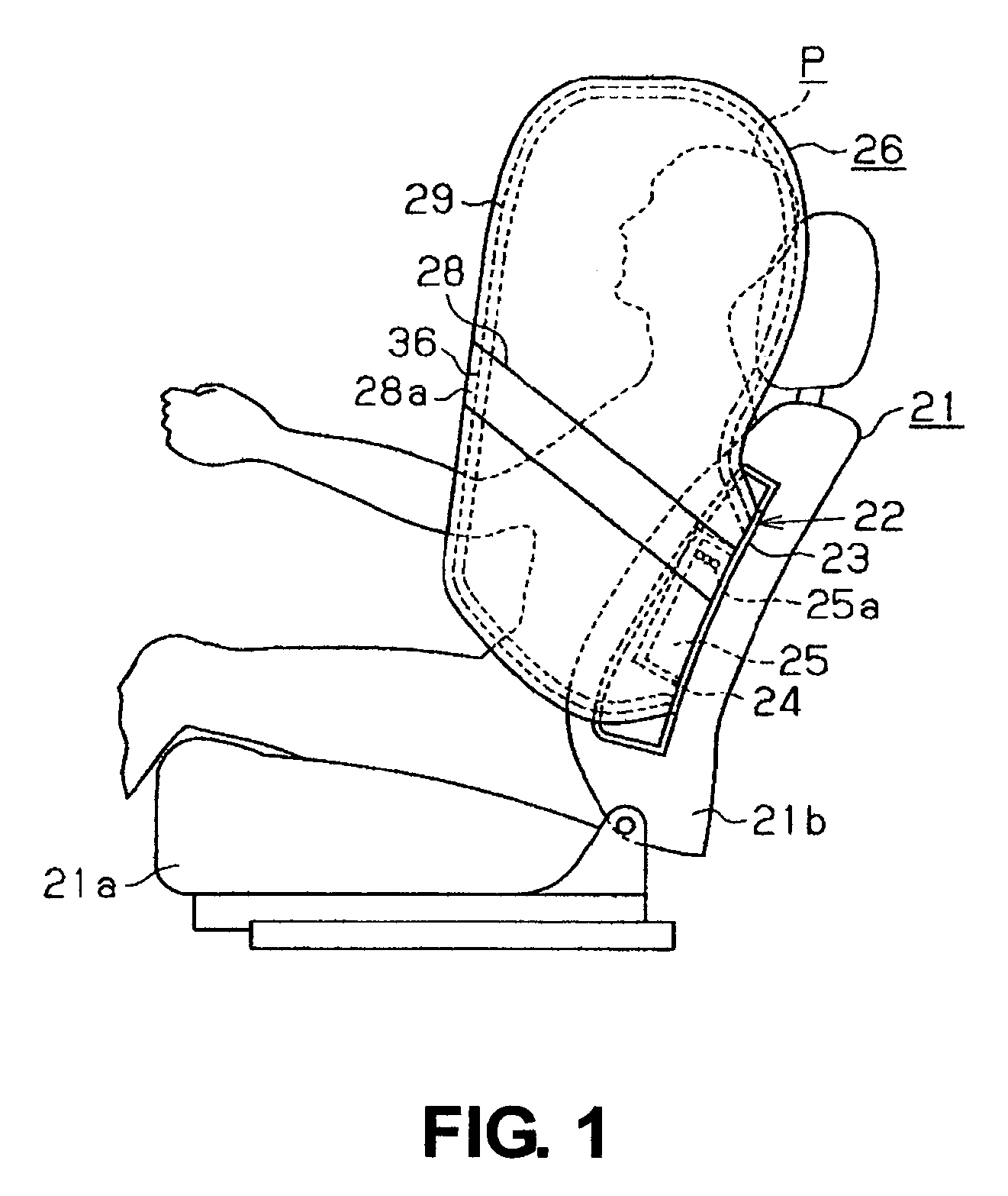
[0016] Referring to FIG. 1, a first embodiment of the present invention will be now explained. In this description, the term “frontward direction” is defined as the direction of travel of a vehicle. Unless extra explanation is added, directions are based on reference to the traveling direction of a vehicle.

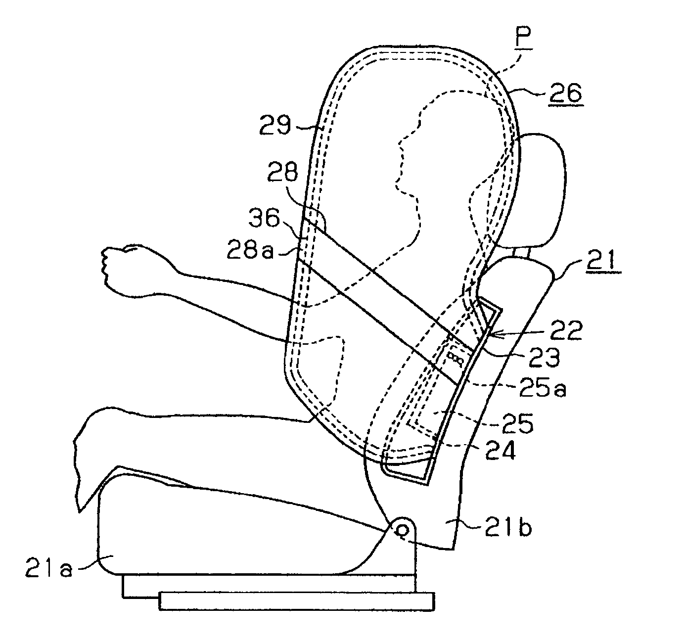
[0017]FIG. 1 shows a front seat 21 that is fixed on a left side of a vehicle. The front seat 21 includes a stool 21a and a seat back 21b. A side air bag device 22 assembled in a case 23 is mounted in the outside (left side) of the seat back 21b of the front seat 21. The side air bag device 22 is fixed corresponding to the position of a door (not shown) which forms a part of the vehicle body side. FIG. 1 shows only the front seat 21 on the left side of the vehicle, but the front seat 21 on the right side of the vehicle also includes the air bag device 22 in the right side of the front seat 21.

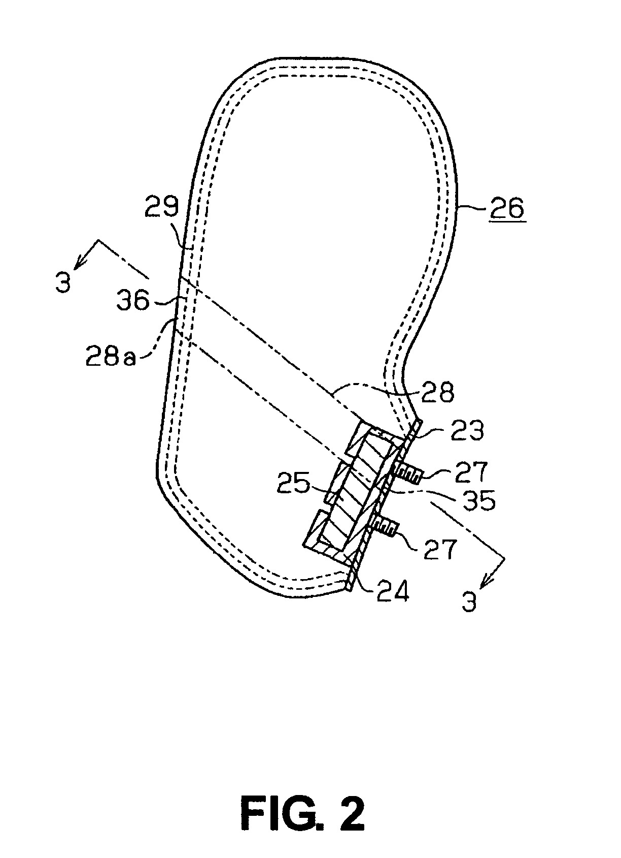
[0018] As shown in FIGS. 1 and 2, the side air bag device 22 includes a tube-like retain...

second embodiment

[0026] The air bag device according to the second embodiment of the present invention will now be explained primarily by discussing the differences between the first embodiment and the second embodiment.

[0027] As shown in FIG. 4, an air bag 26 according to the second embodiment is formed to be expanded between the body side of the vehicle and a passenger P, especially from thorax region to the hip region of the passenger P. A front seat 21 includes a seat back 21b and a stool 21a. The seat back 21b can be folded to overlap the stool 21a, and the seat back 21b can be used as a table. A hinge 30 for folding the seat back 21b projects at the lower side of the seat back 21b. Therefore, a case 23 and a side air bag device 22 are fixed above the hinge 30.

[0028] As shown in FIGS. 5 and 6, an inner tube 40 that is located within the air bag 26 completely covers a retainer 24. The inner tube 40 is placed between the retainer 24 and the case 23 and is fixed with the air bag 26 by bolts 27. ...


PUM


Abstract

A side air bag is expanded by gas discharged from an inflator between a side body of a vehicle and a vehicle front seat. The air bag is fixed with a case in a seat back of the front seat, and expands in a vehicle frontward direction. A belt is sewn to the air bag at a portion where the air bag is fixed to the case and at a seamed front portion of the air bag. The belt creates a tensile force on the air bag that restricts frontward directional deviation of the air bag during expansion.

Description

CROSS REFERENCE TO RELATED APPLICATION [0001] This application is based on and incorporates by reference Japanese Patent Application No. 2004-217610, which was filed on Jul. 26, 2004. BACKGROUND OF THE INVENTION [0002] The present invention relates to side air bags, and more particularly to a side air bag with a directional expansion belt that causes the air bag to expand in a predetermined direction. [0003] A conventional side air bag is designed to expand within a vehicle passenger compartment in an area between a vehicle door and a vehicle passenger seat when the vehicle is involved in a collision and a side impact force is exerted on the side body of the vehicle. The air bag absorbs the shock caused by the side impact force, and protects the head region, the thoracic region and the hip region of the passenger. [0004] At the time of the collision, a high pressure gas discharged from an inflator quickly expands the air bag. The air bag must also expand in a controlled manner based...

Claims


Application Information

Patent Timeline
Patent Type & Authority Applications(United States)
IPC IPC(8): B60R21/16B60R21/20B60R21/207B60R21/2338B60R21/2346
CPCB60R21/23138B60R21/2338B60R2021/23386B60R2021/23382B60R21/2346
Inventor SHIBAYAMA, KOJISATO, YUJINARUSE, MOTOAKIMABUCHI, SATOSHI
Owner TOYODA GOSEI CO LTD
Learn More