Cylinder lock device

Inactive Publication Date: 2006-03-02
ALPHA
View PDF21 Cites 11 Cited by
  • Summary
  • Abstract
  • Description
  • Claims
  • Application Information

AI Technical Summary

Benefits of technology

[0010] One or more embodiments of the present invention provide a cylinder lock capable of increasing different locking codes.
[0016] According to one or more embodiments of the invention, moreover, the moving direction center axes are offset from the turning center of the plug. This enlarges the height difference of the tumbler pins due to the turns. Even at a small turning angle, therefore, the height for closing the turning boundary between the plug and the cylinder case is increased to improve the locking reliability.
[0028] In this case, the rotational centers of the conical faces of the unlocking code forming recesses are arranged on one selected in a predetermined order from three rows, which are aligned at their center with the projection line in the moving direction of the tumbler array. With this arrangement, it is easy to manage the codes and the manufacture of the unlocking key.

Problems solved by technology

As a result, the cylinder lock, as disclosed in JP-A-2003-129710, cannot be increased the number of different locking codes drastically.
However, the cylinder lock of JP-B-07-030641 is defective in that the unlocking key can be copied merely by tracing the cut angles of the original key.

Method used


Image

  • Cylinder lock device
  • Cylinder lock device
  • Cylinder lock device

Examples


embodiment 1

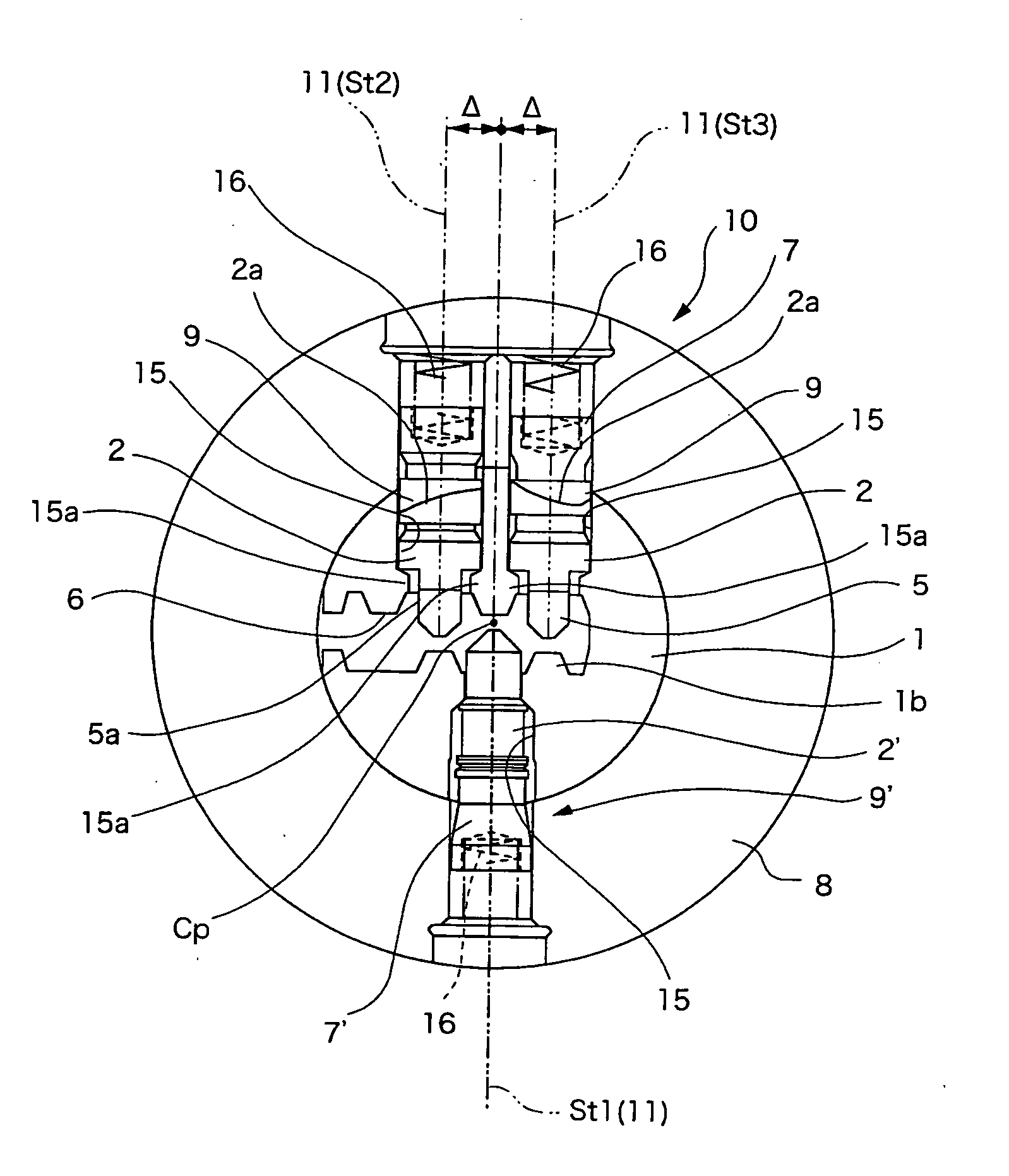
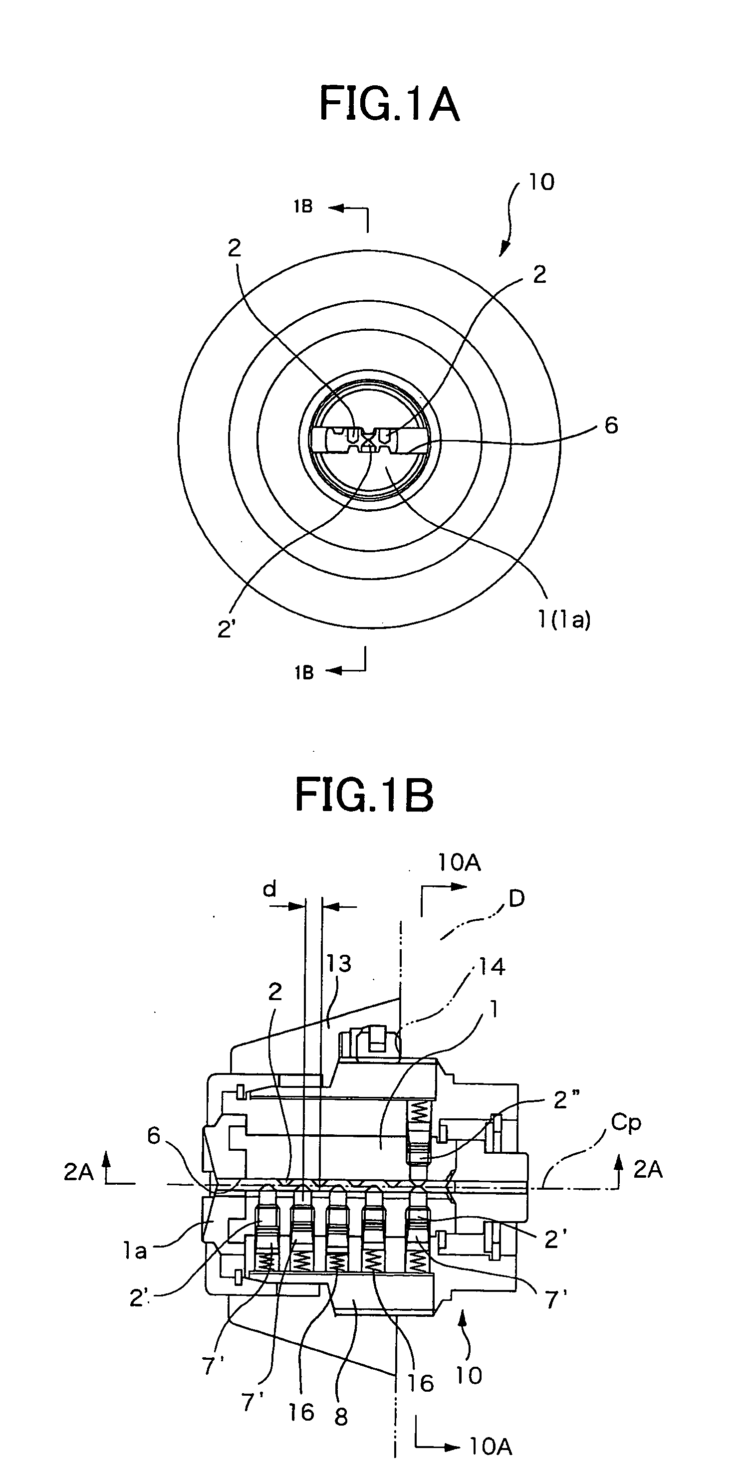
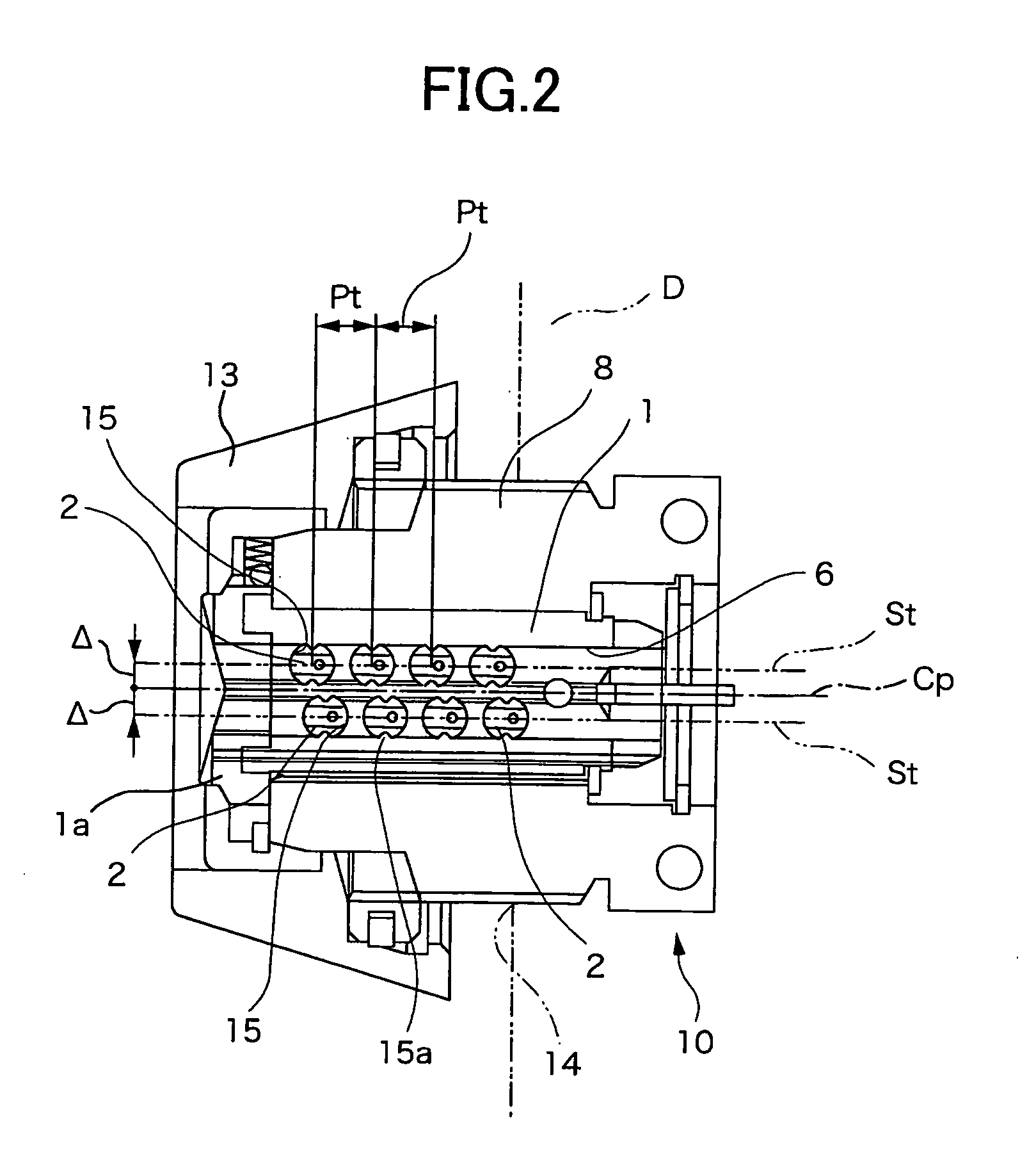
[0052]FIG. 1A to FIG. 2 show a cylinder lock 10, which is fixed on a door body (D) and used for operating the lock body in the door body (D). The cylinder lock 10 is formed by inserting a plug 1 turnably into a cylinder case 8, and a cylindrical cover 13 is fitted in the front end portion of the cylinder case 8. The cylindrical cover 13 can be moved by a turning operation to the surface side of the door body (D). After the cylinder lock 10 was fixed in the state shown in FIG. 2 in the door body (D), the cylindrical cover can be fastened to cover a mounting hole 14 opened in the door body (D), as shown in FIG. 1B. Moreover, a cap member la is fitted in the front end of the plug 1.

[0053] In the center portion of the plug 1, as shown in FIGS. 2 and 4, there is opened a key insertion portion 6, which longitudinally extends of the plug 1. There are also formed a plurality of tumbler insertion holes 15, which are opened at one end in the key insertion portion 6 and at the other end in th...

embodiment 2

[0079]FIG. 11 shows another embodiment of the invention. In this embodiment, the locking portion 9 is constituted to include the tumbler pins 2 and a side bar 12. The upper ends of the tumbler pins 2 and the leading ends of the drive pins 7 are formed like the auxiliary tumbler pins 2′ into the frustum-conical shape. Moreover, the tumbler pins 2 are provided at their lower ends with the drive portions 5 and in their side walls with relief grooves 20 over a predetermined length.

[0080] The numeral 12 designates the side bar, which is so moved perpendicularly of the moving direction center axis 11 as to go into and out of the tumbler insertion hole 15. The cylinder case 8 is provided with a stopper groove 21, which confronts the side bar 12 when the plug is at the turned locking position.

[0081] In case the unlocking code forming recesses 3 have different depths, the boundary between the tumbler pins 2 and the drive pins 7 urged toward the center by the compression springs 16 do not c...


PUM


Abstract

Tumbler pins 2 are movably housed in a plug 1. A locked / unlocked state is determined by the turning position on the moving direction center axes of the tumbler pins 2. An unlocking key 4 to be inserted into the plug 1 is provided with unlocking code forming recesses 3 for determining the turning positions of the tumbler pins at code decision positions. The tumbler pins 2 are provided at their leading end portions with drive portions 5, which have slope sides of conical faces gradually reduced in diameter toward the leading ends and having rotational centers offset from the moving direction center axes. The side wall faces of the unlocking code forming recesses 3 are formed of conical faces having rotational centers substantially aligned with those of the conical faces forming the slope sides of the drive portions 5. At code decision positions, the slope sides of the drive portions 5 are forced to contact with the side wall faces of the unlocking code forming recesses 3 thereby to determine the turning positions of the tumbler pins2.

Description

[0001] The present application claims foreign priority based on Japanese Patent Application Nos. P.2004-254916 filed on Sep. 1, 2004, and P.2004-254917 filed on Sep. 1, 2004, the contents of which are incorporated herein by reference. BACKGROUND OF THE INVENTION [0002] 1. Field of the Invention [0003] The present invention relates to a cylinder lock device. [0004] 2. Related Art [0005] JP-A-2003-129710 discloses a cylinder lock using pin tumblers. The cylinder lock of JP-A-2003-129710 is formed by housing individual pin tumblers in a plug and a cylinder case. When a genuine unlocking key is inserted into the plug, boundaries of the pin tumblers move to a turning boundary of the plug in accordance with a depth of unlocking code forming recesses formed in the unlocking key, so that the key can be turned in the plug. [0006] However, a discrimination of the key depends exclusively on the depths of the key code forming recesses. In order to increase different locking codes, therefore, wh...

Claims


Application Information

Patent Timeline
IPC IPC(8): E05B27/06
CPCE05B19/0023E05B27/0082E05B27/0039Y10T70/7565Y10T70/7571Y10T70/7605Y10T70/761Y10T70/7881
Inventor OSADA, SHUNICHI
Owner ALPHA
Why Eureka
Try Eureka