Developing apparatus

a technology of developing apparatus and developer container, which is applied in the direction of electrographic process apparatus, instruments, optics, etc., can solve the problems of difficult stirring of the spring track of the stirring portion, difficult setup, etc., and achieve the effect of preventing the deterioration of the developer in the developer container and preventing the specific portion of the developer container from deterioration

Active Publication Date: 2006-03-02
CANON KK
View PDF39 Cites 13 Cited by
  • Summary
  • Abstract
  • Description
  • Claims
  • Application Information

AI Technical Summary

Benefits of technology

[0016] Further, according to the present invention, the problem that the developer in the developer container is not stirred in its entirety can be prevented. Therefore, the problem that the developer deterioration occurs in specific portions of the developer container can be prevented. Therefore, the deterioration of the developer in the developer container can be minimized.

Problems solved by technology

However, this setup seems to be problematic in that the body of developer which overlaps with the track of the stirring portion and the tracks of the springs of the stirring portion, as seen from the direction parallel to the axial line of the stirring member, is easily stirred, but the body of developer which does not overlap with the track of the stirring portion and the tracks of the springs of the stirring portion is not easily stirred.

Method used


Image

  • Developing apparatus
  • Developing apparatus
  • Developing apparatus

Examples


embodiment 1

[Embodiment 1]

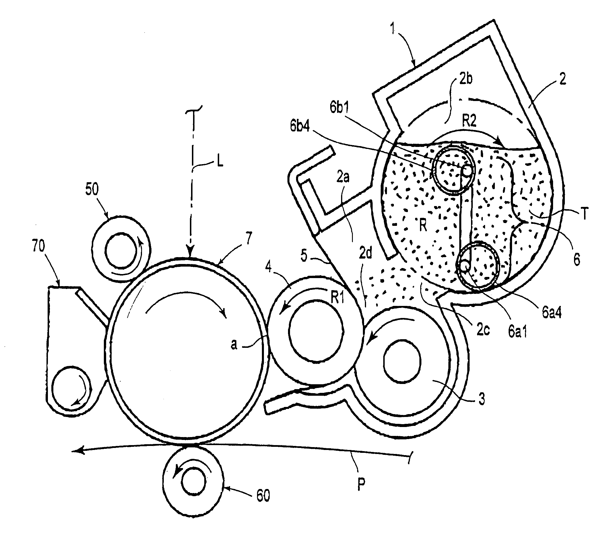
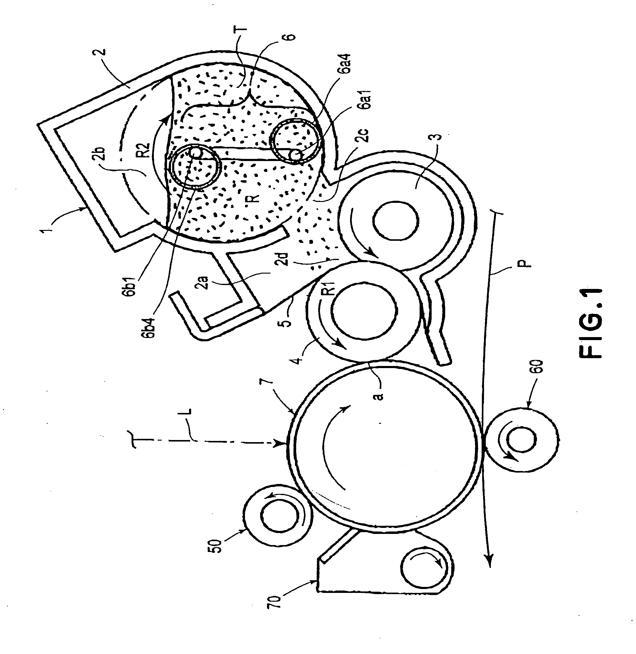
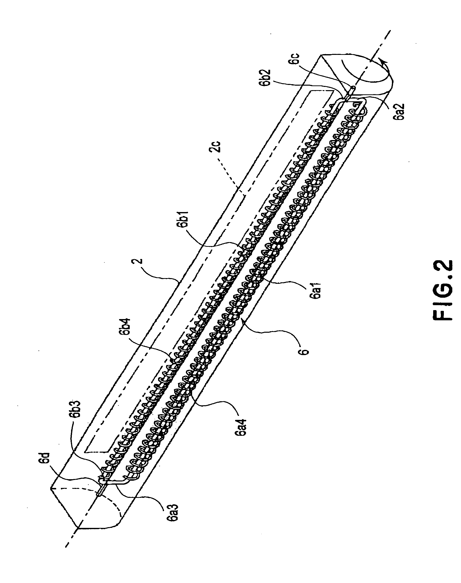
[0029] Next, the first embodiment of the present invention will be described with reference to the appended drawings. FIG. 1 is a schematic drawing of the electrophotographic image forming apparatus employing the developing apparatus in this embodiment, showing the general structure thereof. FIG. 2 is a perspective view of the developer stirring member in this embodiment. FIG. 3 is a schematic sectional view of the developer container in this embodiment, showing how the developer is stirred by the developer stirring member in the developer container. FIG. 4 is a plan view of the developer stirring chamber, showing how the developer is stirred by the developer stirring member. FIG. 5 is a sectional view of the stirring chamber of the developing apparatus, showing how the developer is stirred in the stirring chamber of the developing apparatus.

[0030] Designated by a referential number 7 in FIG. 1 is an electrophotographic photosensitive member in the form of a rotationa...

embodiment 2

[Embodiment 2]

[0062] Next, the second embodiment of the present invention will be described. FIG. 6 is a perspective view of the developer stirring member in this embodiment. The structural features of the developer stirring member in this embodiment, which are identical to those shown in FIG. 2 will not be described here.

[0063] In this embodiment, the rotational stirring portions 6a1 and 6b1 of the stirring member 6 are externally fitted with a plurality of mobile stirring portions 6a5 and 6b5 in the form of a circular ring, the internal diameters of which are greater than the external diameters of the rotational stirring portions 6a1 and 6b1, respectively. In other words, in this embodiment, the mobile stirring portions 6a5 and 6b5 are allowed to move relative to the rotational stirring portions 6a1 and 6b1, respectively, in their radius directions.

[0064]FIG. 7(a) is an enlarged perspective view of one of the plurality of mobile stirring portions 6a5 (6b5), and FIG. 7(b) is a se...

embodiment 3

[Embodiment 3]

[0073] Next, the third embodiment of the present invention will be described. FIG. 9 is a sectional view of the process cartridge, which comprises the developing apparatus in this embodiment and a developer supply container for supplying the developing apparatus with developer. FIG. 10 is a sectional view of the right-hand portion (in FIG. 9) of the developing apparatus, inclusive of a developer container, at a plane parallel to the lengthwise direction. FIG. 11 is an external perspective view is of the developer stirring member in this embodiment.

[0074] The structural features of the stirring member, in this embodiment, identical to those in the first embodiment, will not be described here.

{Process Cartridge}

[0075] Referring to FIG. 9, a process cartridge 17 comprises a cleaning unit 17A, and a development unit 17B as a developing apparatus, which are integrally connected to each other.

[0076] The cleaning unit 17A has a cleaning means container 17A1 as a frame for...


PUM


Abstract

A developing apparatus for developing an latent image formed on an electrophotographic photosensitive member with a developer in an electrophotographic image forming apparatus, the developing device includes a developer accommodating portion for accommodating the developer to be supplied to the developing member; a developer stirring member for stirring the developer in the developer accommodating portion, the developer stirring member including a rotatable member rotatably provided in the developer accommodating portion, a first stirring rotatable portion provided on the rotatable member, a first movable stirring portion movably provided on the first stirring rotatable portion, a second stirring rotatable portion provided on the rotatable member, and a second movable stirring portion movably provided on the second stirring rotatable portion, and wherein a radius of rotation of the first stirring rotatable portion and a radius of rotation of the second stirring rotatable portion are different from each other, and a part of a stirring region in which the first stirring rotatable portion and the first movable stirring portion stirs the developer and a part of a stirring region in which the second stirring rotatable portion and the second movable stirring portion stirs the developer, are overlapped.

Description

FIELD OF THE INVENTION AND RELATED ART [0001] The present invention relates to a developing apparatus employed by an electrophotographic image forming apparatus for forming an image on recording medium with the use of one of the electrophotographic image forming methods, a development cartridge removably mountable in the main assembly of an electrophotographic image forming apparatus, and a process cartridge removably mountable in the main assembly of an electrophotographic image forming apparatus. [0002] Here, a developing apparatus means an apparatus having a developing member for developing an electrostatic latent image formed on an electrophotographic photosensitive member. A development cartridge means a cartridge, that is, a unit, in which a developing member is disposed, and which is removably mountable in the main assembly of an electrophotographic image forming apparatus. Further, a process cartridge means a cartridge, that is, a unit, in which an electrophotographic photos...

Claims


Application Information

Patent Timeline
Patent Type & Authority Applications(United States)
IPC IPC(8): G03G15/08
CPCG03G2215/085G03G15/0822
Inventor KAWAI, TACHIOYAMAGUCHI, SAIJIKAWASAKI, SYUHEI
Owner CANON KK
Why Eureka
Try Eureka