Developing apparatus
a technology of developing apparatus and developer container, which is applied in the direction of electrographic process apparatus, instruments, optics, etc., can solve the problems of difficult stirring of the spring track of the stirring portion, troublesome setup, etc., and achieve the goal of preventing and minimizing the deterioration of the developer in the developer container
- Summary
- Abstract
- Description
- Claims
- Application Information
AI Technical Summary
Benefits of technology
Problems solved by technology
Method used
Image
Examples
embodiment 1
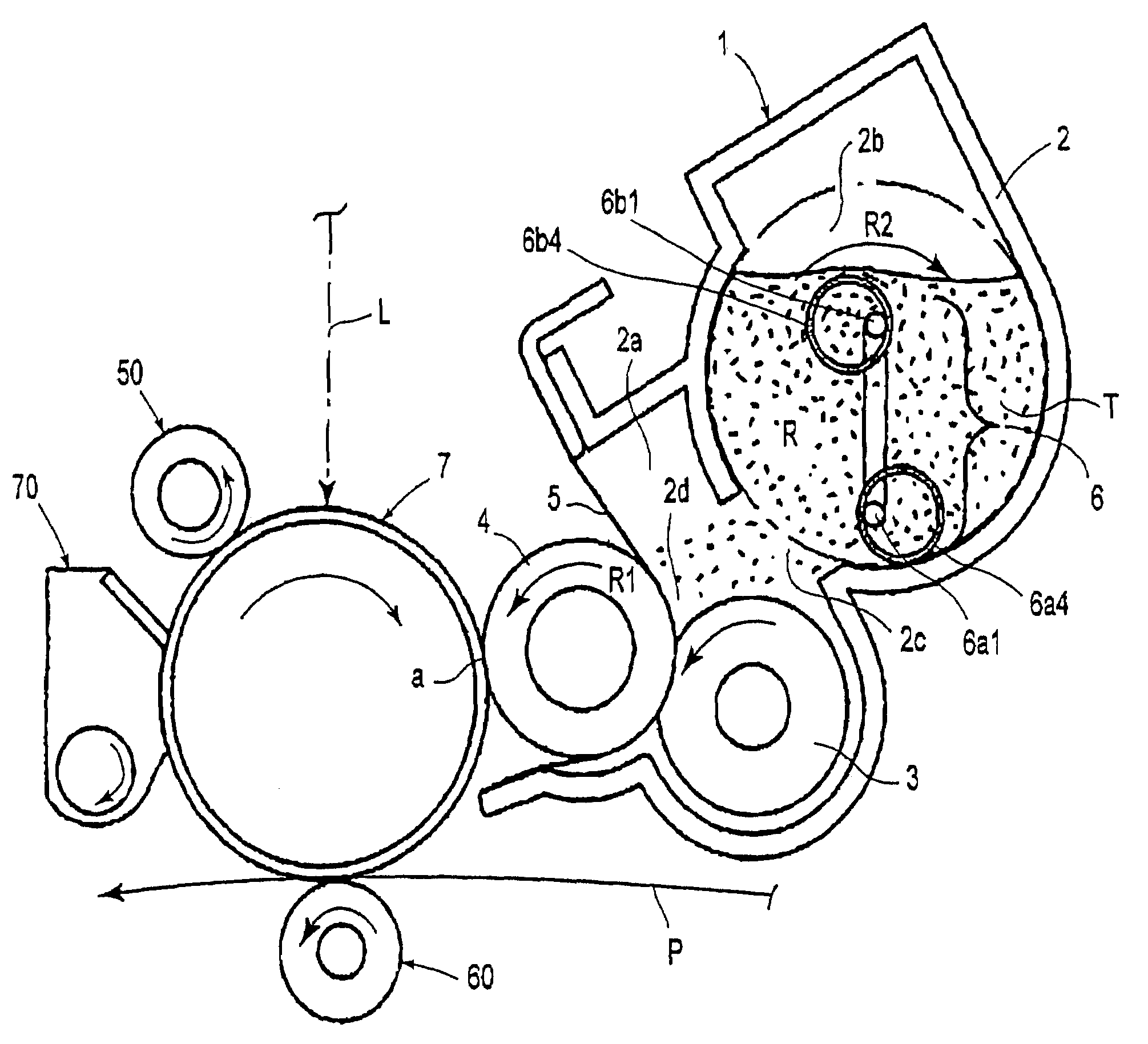
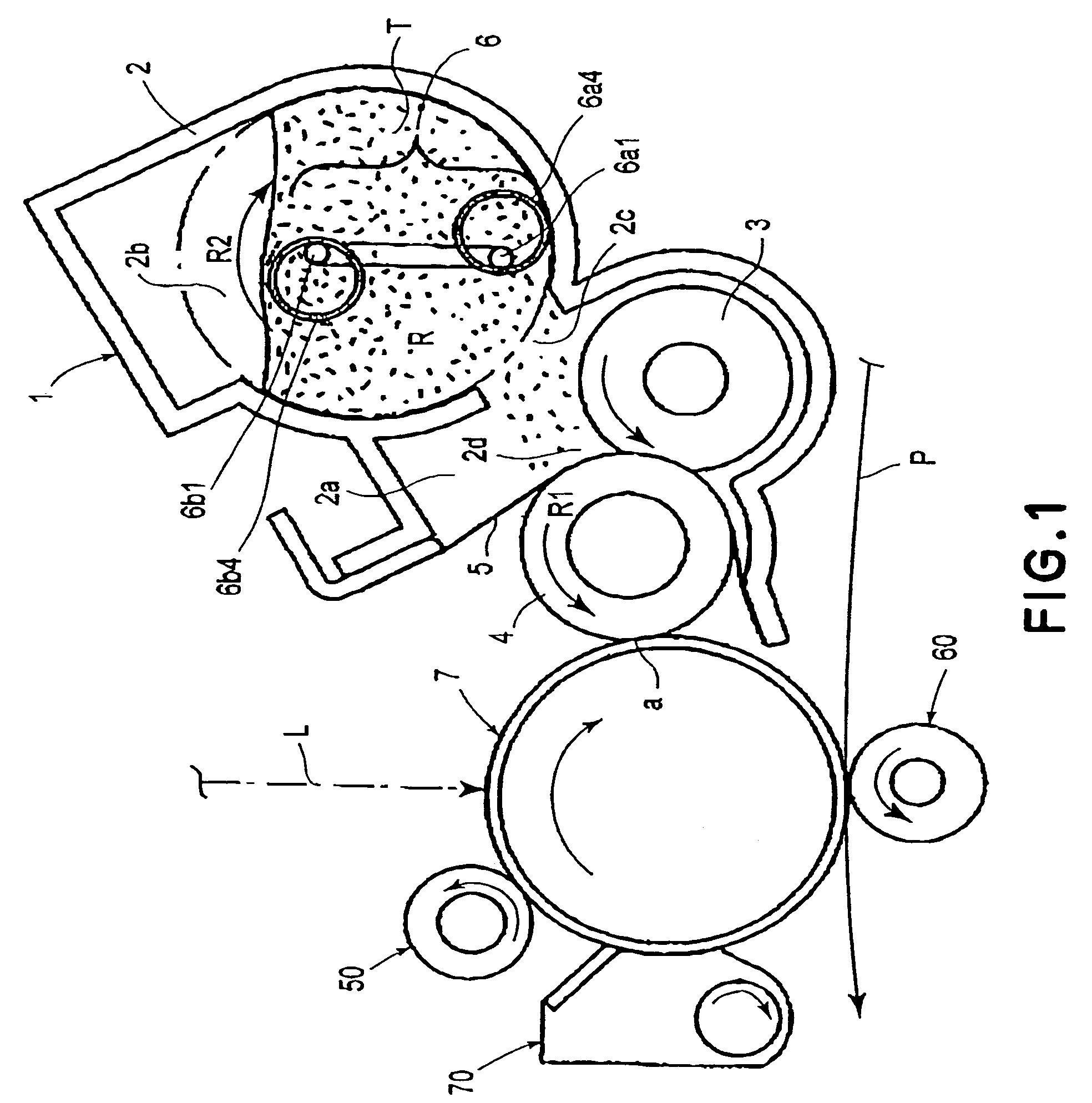
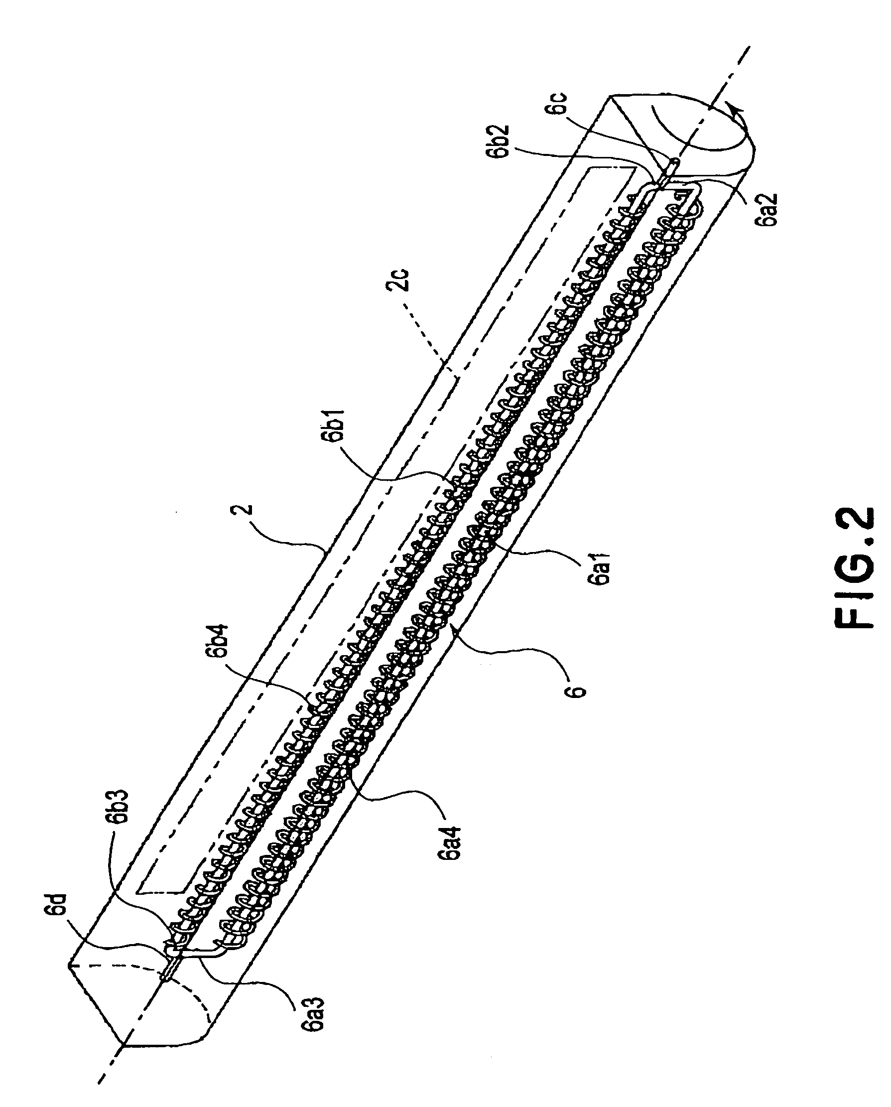
[0029]Next, the first embodiment of the present invention will be described with reference to the appended drawings. FIG. 1 is a schematic drawing of the electrophotographic image forming apparatus employing the developing apparatus in this embodiment, showing the general structure thereof. FIG. 2 is a perspective view of the developer stirring member in this embodiment. FIG. 3 is a schematic sectional view of the developer container in this embodiment, showing how the developer is stirred by the developer stirring member in the developer container. FIG. 4 is a plan view of the developer stirring chamber, showing how the developer is stirred by the developer stirring member. FIG. 5 is a sectional view of the stirring chamber of the developing apparatus, showing how the developer is stirred in the stirring chamber of the developing apparatus.
[0030]Designated by a reference numeral 7 in FIG. 1 is an electrophotographic photosensitive member in the form of a rotational drum (which here...
embodiment 2
[0064]Next, the second embodiment of the present invention will be described. FIG. 6 is a perspective view of the developer stirring member in this embodiment. The structural features of the developer stirring member in this embodiment, which are identical to those shown in FIG. 2 will not be described here.
[0065]In this embodiment, the rotational stirring portions 6a1 and 6b1 of the stirring member 6 are externally fitted with a plurality of mobile stirring portions 6a5 and 6b5 in the form of a circular ring, the internal diameters of which are greater than the external diameters of the rotational stirring portions 6a1 and 6b1, respectively. In other words, in this embodiment, the mobile stirring portions 6a5 and 6b5 are allowed to move relative to the rotational stirring portions 6a1 and 6b1, respectively, in their radius directions.
[0066]FIG. 7(a) is an enlarged perspective view of one of the plurality of mobile stirring portions 6a5 (6b5), and FIG. 7(b) is a sectional view of th...
embodiment 3
[0075]Next, the third embodiment of the present invention will be described. FIG. 9 is a sectional view of the process cartridge, which comprises the developing apparatus in this embodiment and a developer supply container for supplying the developing apparatus with developer. FIG. 10 is a sectional view of the right-hand portion (in FIG. 9) of the developing apparatus, inclusive of a developer container, at a plane parallel to the lengthwise direction. FIG. 11 is an external perspective view is of the developer stirring member in this embodiment.
[0076]The structural features of the stirring member, in this embodiment, identical to those in the first embodiment, will not be described here.
[Process Cartridge]
[0077]Referring to FIG. 9, a process cartridge 17 comprises a cleaning unit 17A, and a development unit 17B as a developing apparatus, which are integrally connected to each other.
[0078]The cleaning unit 17A has a cleaning means container 17A1 as a frame for rotatably supporting ...
PUM
 Abstract
Description
Claims
Application Information
 - R&D
- Intellectual Property
- Life Sciences
- Materials
- Tech Scout
- Unparalleled Data Quality
- Higher Quality Content
- 60% Fewer Hallucinations
Browse by: Latest US Patents, China's latest patents, Technical Efficacy Thesaurus, Application Domain, Technology Topic, Popular Technical Reports.
© 2025 PatSnap. All rights reserved.Legal|Privacy policy|Modern Slavery Act Transparency Statement|Sitemap|About US| Contact US: help@patsnap.com


