Selectively movable motorcycle stand

a motorcycle stand and selectable technology, applied in the field of stands, can solve the problem that the stand or the lift base cannot be easily moved along the support surface, and achieve the effect of improving the service life and reducing the maintenance cos

Inactive Publication Date: 2006-03-02
WARNER PATRICK A +1
View PDF22 Cites 15 Cited by
  • Summary
  • Abstract
  • Description
  • Claims
  • Application Information

AI Technical Summary

Benefits of technology

[0006] The present invention provides various embodiments of stands and lift bases capable of supporting various objects above a support surface, such as a floor or the ground. The stands and lift bases are configurable between a stationary configuration and a mobile configuration. The stands may include a frame and a top adapted to support various objects, and the lift bases may include a base adapted support a stationary stand. Embodiments of the stands and lift bases include a lift device that can be operated to engage or disengage wheels or rollers with the support surface to place the stand or base in stationary and mobile configurations. When in the mobile configuration, the stand or lift base is rollingly sup...

Problems solved by technology

When placed in the stationary configuration, one or more wheels are disengaged with the s...

Method used


Image

  • Selectively movable motorcycle stand
  • Selectively movable motorcycle stand
  • Selectively movable motorcycle stand

Examples


first embodiment

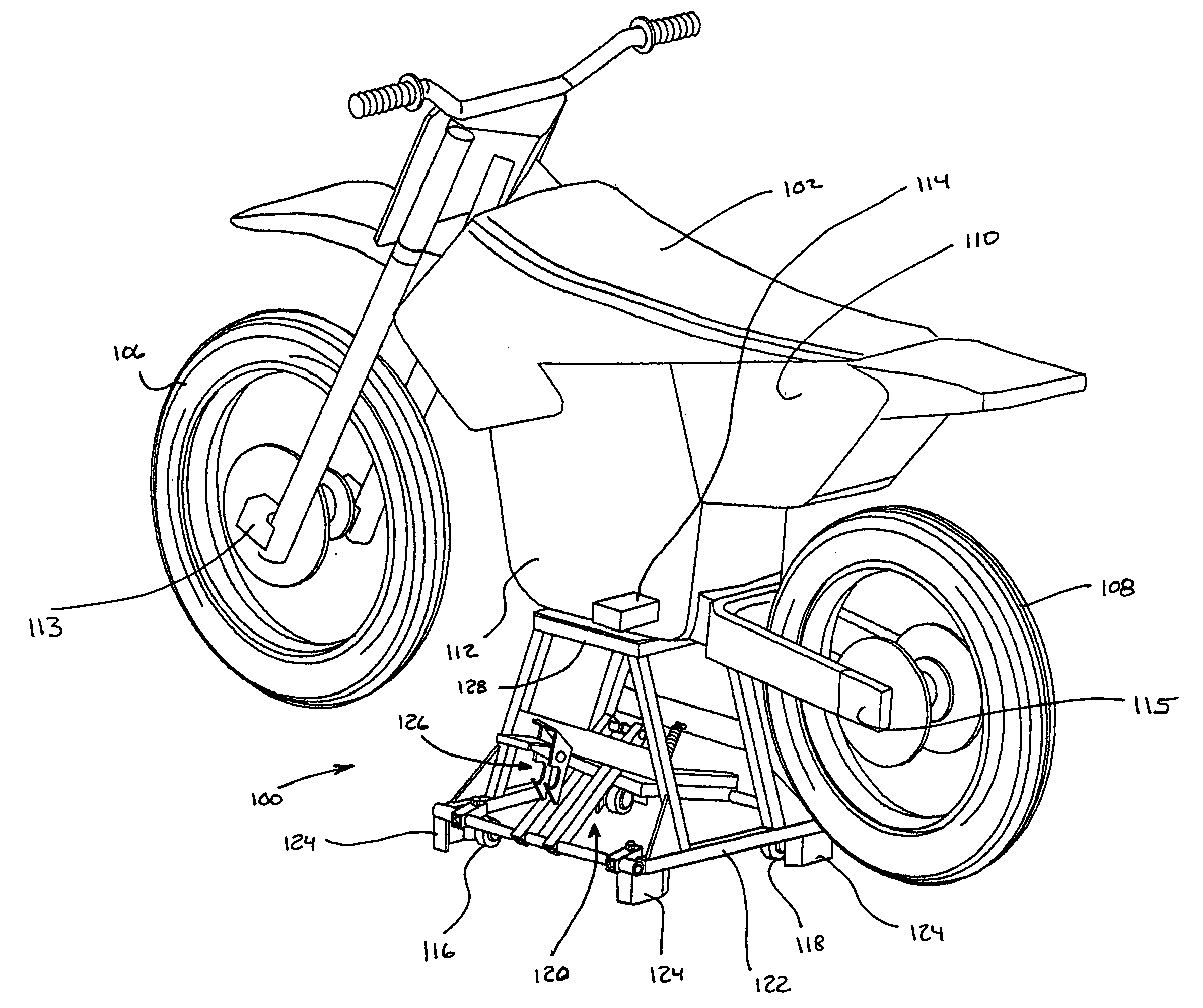
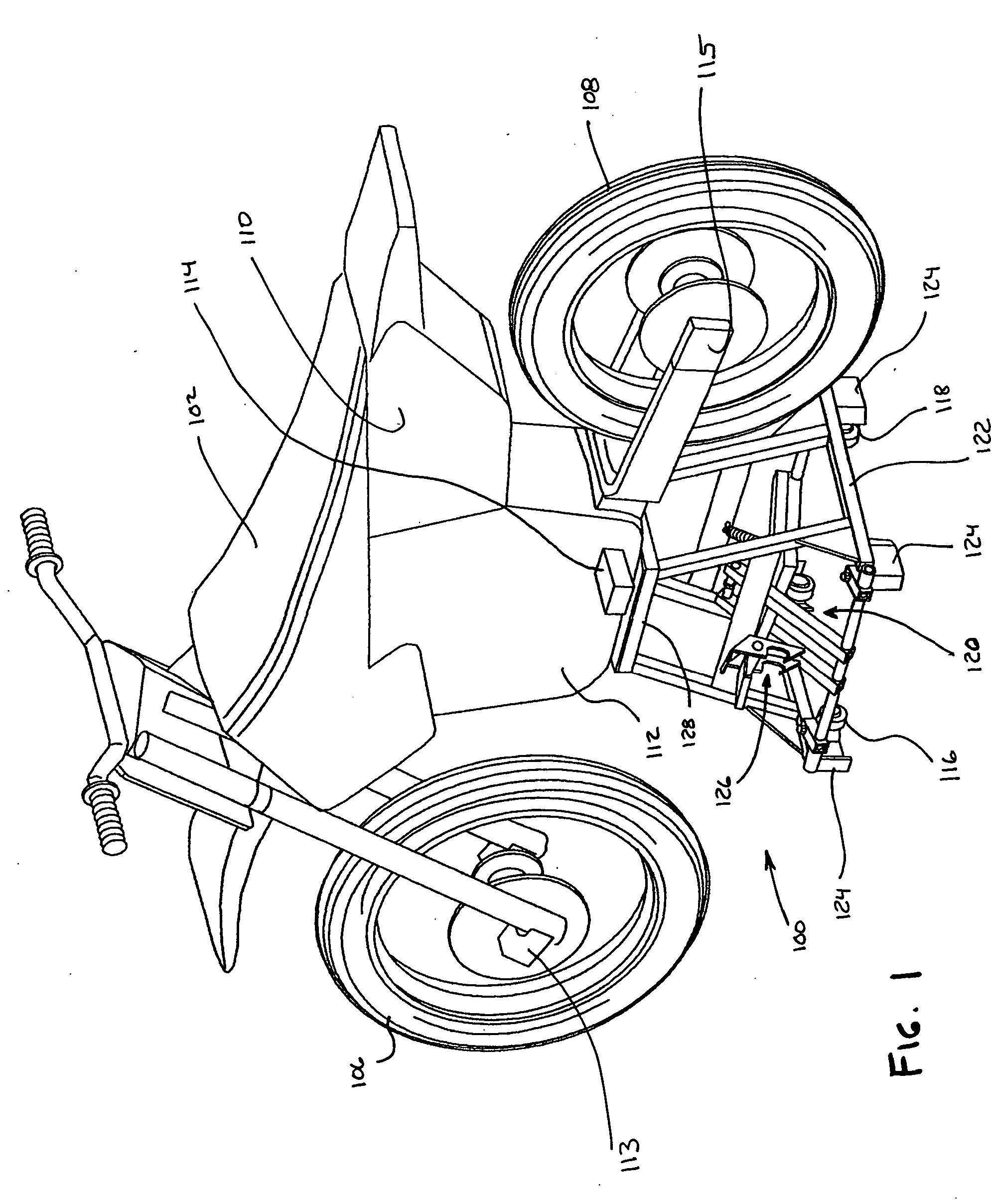
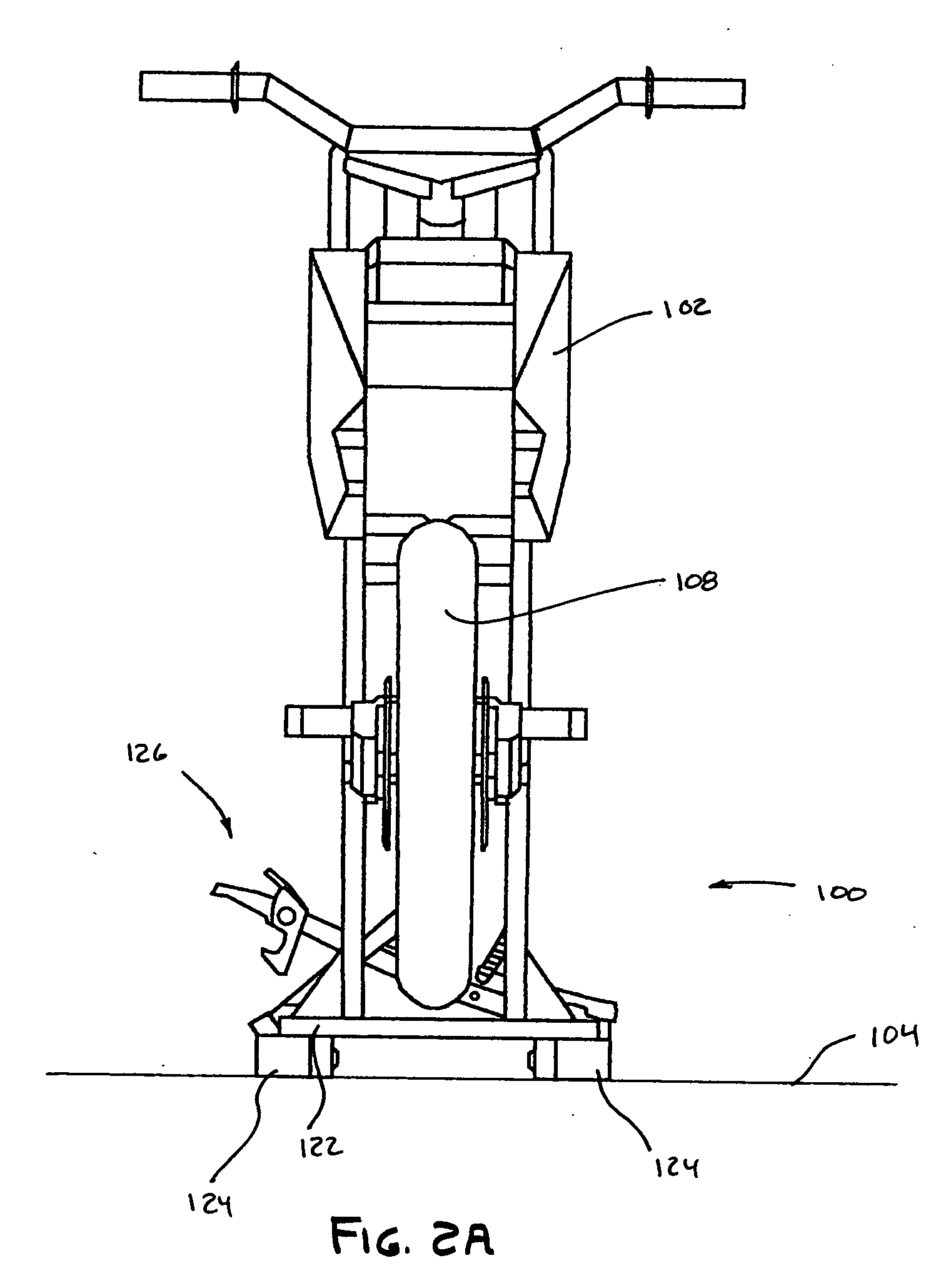
[0072]FIGS. 4A-6B show additional views of the stand shown in FIGS. 1-3C. More particularly, FIGS. 4A-4E illustrate various views of the stand in the stationary configuration, and FIGS. 5A-5E illustrate various views of the stand in the mobile configuration. As shown in FIGS. 4A and 5A, the stand 100 includes a stand top 128 connected with an upper portion 130 of the frame 122. The stand top 128 provides an area 132 upon which an object that is to be supported can be placed, such as a motorcycle. The upper portion 130 of the frame 122 is supported by and extends upward from a base portion 134. Although the frame is described and depicted below with a certain degree of particularity, it is to be appreciated that various embodiments of the stand can utilize other types of frame forms and structures and should not be construed to limit the frame to what is depicted and described herein.

[0073] As shown in FIGS. 4A and 5A, the base portion 134 of the frame 122 includes a right pivot supp...

embodiment 100

[0103]FIGS. 10A and 10B are right side cross sectional views of a first alternative embodiment of a stand 338 with a lift device 340 having a threaded crank shaft 342 that controls the movement of first and second threaded links 344, 346, which allows a user to place the stand 338 in the mobile and stationary configurations. More particularly, the threaded links 344, 346 are coupled with first and second lift mechanisms 348, 350, respectively, and as such, the movement of the threaded links in a particular direction cause the lift mechanisms to engage and / or disengage the wheels 116, 118 with the support surface. As described above with reference to the first stand embodiment 100, the first and second lift mechanisms 348, 350 shown in FIGS. 10A and 10B each include first and second lift axles 192, 256 pivotally coupled with the frame 122. In addition, the rear and forward caster wheels 118, 116 are coupled with the first and second lift axles, respectively, through caster wheel moun...

embodiment 450

[0124] As previously discussed, the stand embodiment 450 shown in FIGS. 14A and 14B provides linkage assemblies that maintain the caster wheel mounts in substantially vertical orientations as the wheels are engaged and disengaged with the support surface. It is to be appreciated that the wheels can be coupled with the frame and lift mechanisms in other ways to provide for similar caster wheel movements. For example, FIGS. 15A and 15B show an alternative manner in which the wheels can be coupled with the frame and the lift mechanisms. As illustrated, the connection post 224 of the caster wheel 208 assembly can extend upward through an aperture 486 in the frame 122. As such, the connection post 224 is adapted to slide up and down through the aperture 486 in the frame when placing the stand in the mobile and stationary configurations. FIGS. 15A and 15B also illustrate that the wheel assemblies 208 need not be connected directly with a lift mechanism 488, but instead, can be configured ...


PUM


Abstract

The present invention provides various embodiments of stands and lift bases capable of supporting various objects above a support surface. The stands and lift bases are configurable between a stationary and mobile configurations. The stands may include a frame and a top adapted to support various objects, and the lift bases may include a base adapted support a stationary stand. Embodiments of the stands and lift bases include a lift device that can be operated to engage or disengage wheels or rollers with the support surface to place the stand or base in stationary and mobile configurations. When in the mobile configuration, the stand or lift base is rollingly supported on the wheels or rollers. Some embodiments of the stands and lift bases also include locking devices that allow the user to fix the stand or lift base in the mobile and/or stationary configurations.

Description

CROSS-REFERENCE TO RELATED APPLICATIONS [0001] This application claims the benefit of U.S. Provisional Application No. 60 / 674,794, filed on Apr. 25, 2005 and U.S. Provisional Application No. 60 / 576,792, filed on Jun. 2, 2004, which are both hereby incorporated herein by reference.BACKGROUND OF THE INVENTION [0002] a. Field of the Invention [0003] Aspects of this invention relate to stands used to support various objects, such as motorcycles and other types of vehicles above a support surface, some more particular aspects involve stands and lift bases having wheels that can be selectively manipulated to engage the support surface to allow a user to move the stand along the support surface. [0004] b. Background Art [0005] Many currently available motorcycle stands provide a frame upon which a motorcycle can be placed to allow a user to safely perform maintenance and other types of work on the motorcycle. However, many of these motorcycle stands do not allow a user to easily move the s...

Claims


Application Information

Patent Timeline
IPC IPC(8): B60P3/00
CPCB25H1/0014B62B2202/90B62B5/049B60S13/00
Inventor WARNER, PATRICK A.LULL, ANDREW P.
Owner WARNER PATRICK A
Why Eureka
Try Eureka