Nuclear fuel rod

a technology fuel pellets, applied in nuclear energy generation, reactor fuel elements, climate sustainability, etc., can solve the problems of increased fission gas emission, worse conductivity between fuel pellets and claddings, increased pellet temperature, etc., to prevent secondary hydrogenation and improve the resistability of nuclear fuel rods

Active Publication Date: 2006-03-09
WESTINGHOUSE ELECTRIC SWEDEN
View PDF7 Cites 1 Cited by
  • Summary
  • Abstract
  • Description
  • Claims
  • Application Information

AI Technical Summary

Benefits of technology

[0008] The aim of the present invention is to improve a nuclear fuel rod's resistability against secondary degrading. More particularly the invention concerns preventing secondary hydrogenation and a secondary defect after a typical primary defect has occurred

Problems solved by technology

If the thermal conductivity of the fill gas is drastically reduced, compared to the case where the fill gas is substantially constituted of helium only, the th

Method used


Image

  • Nuclear fuel rod
  • Nuclear fuel rod
  • Nuclear fuel rod

Examples


Embodiment Construction

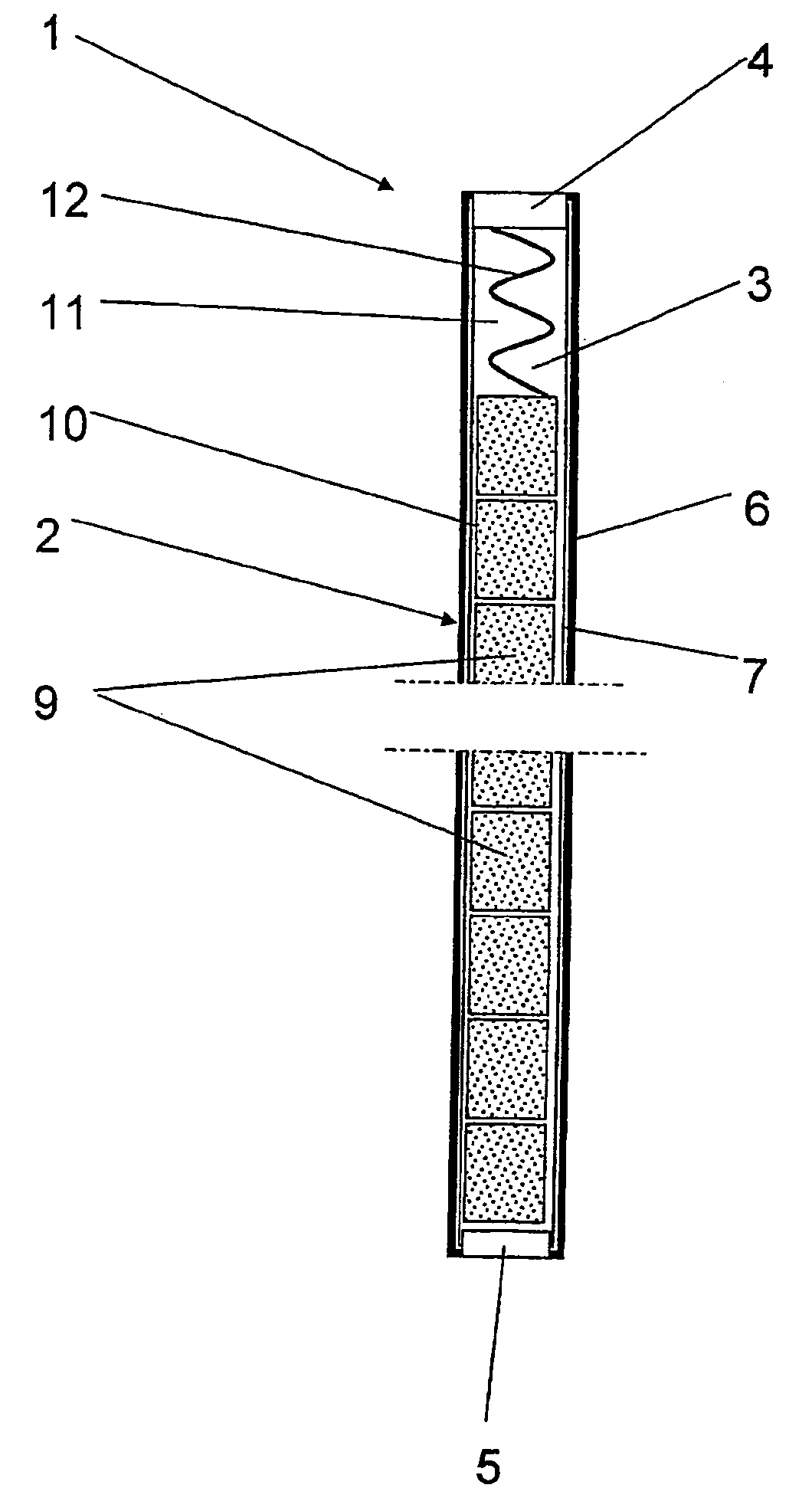
[0035]FIG. 1 schematically shows a nuclear fuel rod 1 for a nuclear reactor of the light water type. The nuclear reactor can be a boiling water reactor (BWR) or a pressurized water reactor (PWR). The nuclear fuel rods comprise a cladding tube 2 that defines a closed inner space 3. The cladding tube 2 has a first upper end that is concluded with a top plug 4 and a second lower end that is concluded with a bottom plug 5.

[0036] The cladding tube 2 is manufactured from at least one of the materials in the group zirconium and a zirconium-based alloy. Such a zirconium-based alloy can be ZIRCALOY-2 or ZIRCA-LOY-4. In the embodiment shown the cladding tube 2 also comprises an outer tube 6 and an inner tube 7, whereby the inner tube 7 forms a so called liner, that is manufactured so that it has a metallic binding to the outer tube 6. The outer tube 6 can be manufactured from any of the above-mentioned zirconium-based alloys while the inner tube 7 can be manufactured of pure zirconium metal....


PUM


Abstract

In a nuclear fuel rod a cladding tube is provided having a closed inner space and manufactured from at least one of the materials in the group zirconium and a zirconium-based alloy, and a pile of nuclear fuel pellets arranged in the inner space in the cladding tube. The nuclear fuel pellets fill part of the inner space. A fill gas is arranged in the closed inner space to fill the rest of the inner space. The internal pressure of the fill gas in the nuclear fuel rod amounts to at least 2 bar (abs) or at least 10 bar (abs). The fill gas contains a proportion of inert gas a proportion of carbon monoxide that is greater than 3 volume percent of the fill gas or greater than 2 volume percent of the fill gas.

Description

BACKGROUND OF THE INVENTION AND PRIOR ART [0001] The present invention concerns a nuclear fuel rod for a nuclear reactor of the boiling water or pressurized water type, comprising a cladding tube that defines a closed inner space and which is manufactured from at least one of the materials in the group zirconium and a zirconium-based alloy, a pile of nuclear fuel pellets arranged in the inner space in the cladding tube so that the nuclear fuel pellets fill part of the inner space, and a fill gas arranged in the closed inner space to fill the rest of the inner space, whereby the fill gas contains a proportion of helium and a proportion of carbon monoxide. The invention also concerns a nuclear fuel assembly comprising such a nuclear fuel rod. Furthermore the invention concerns a method for manufacturing a nuclear fuel rod for a nuclear reactor of the boiling water or pressurized water type. [0002] A nuclear plant comprises a reactor core that is formed from a number of fuel assemblies...

Claims


Application Information

Patent Timeline
IPC IPC(8): G21C3/00G21C3/16G21C21/02
CPCG21C3/16G21C21/02G21Y2002/303Y02E30/40G21Y2004/30G21Y2004/40G21Y2004/10Y02E30/30
Inventor HULTQUIST, GUNNARLIMBACK, MAGNUSTAGTSTROM, PERHORNLUND, ERIK
Owner WESTINGHOUSE ELECTRIC SWEDEN
Why Eureka
Try Eureka