Walking assistance system

a technology of assistance system and walking aid, which is applied in the field of walking assistance system, can solve the problems of putting a large burden on the user, giving the user an uncomfortable sensation, and causing the user to feel uncomfortable while walking

Active Publication Date: 2006-03-23
HONDA MOTOR CO LTD
View PDF4 Cites 176 Cited by
  • Summary
  • Abstract
  • Description
  • Claims
  • Application Information

AI Technical Summary

Benefits of technology

[0014] The embodiment of the present invention prevents an upper leg coupling member provided in an upper leg fr

Problems solved by technology

In this way, when the upper leg supports rub against the upper leg, there is a problem that the skin of the upper leg is pulled, thus giving the user an uncomfortable sensation.
Since the above-mentioned conventional arrangement does not have the degree of freedom to allow the upper leg to swing in the left-and-right direction, the user might feel uncomfortable while walking.
In order to avoid this, the second link, which is positioned along the upper leg, may be formed from a soft material having flexibility and made to follow the movement of the upper leg in the left-and-right direction, but unless the framework of the walking assistance system including the

Method used


Image

  • Walking assistance system
  • Walking assistance system
  • Walking assistance system

Examples


first embodiment

[0061] the present invention is described below by reference to FIG. 1 to FIG. 6.

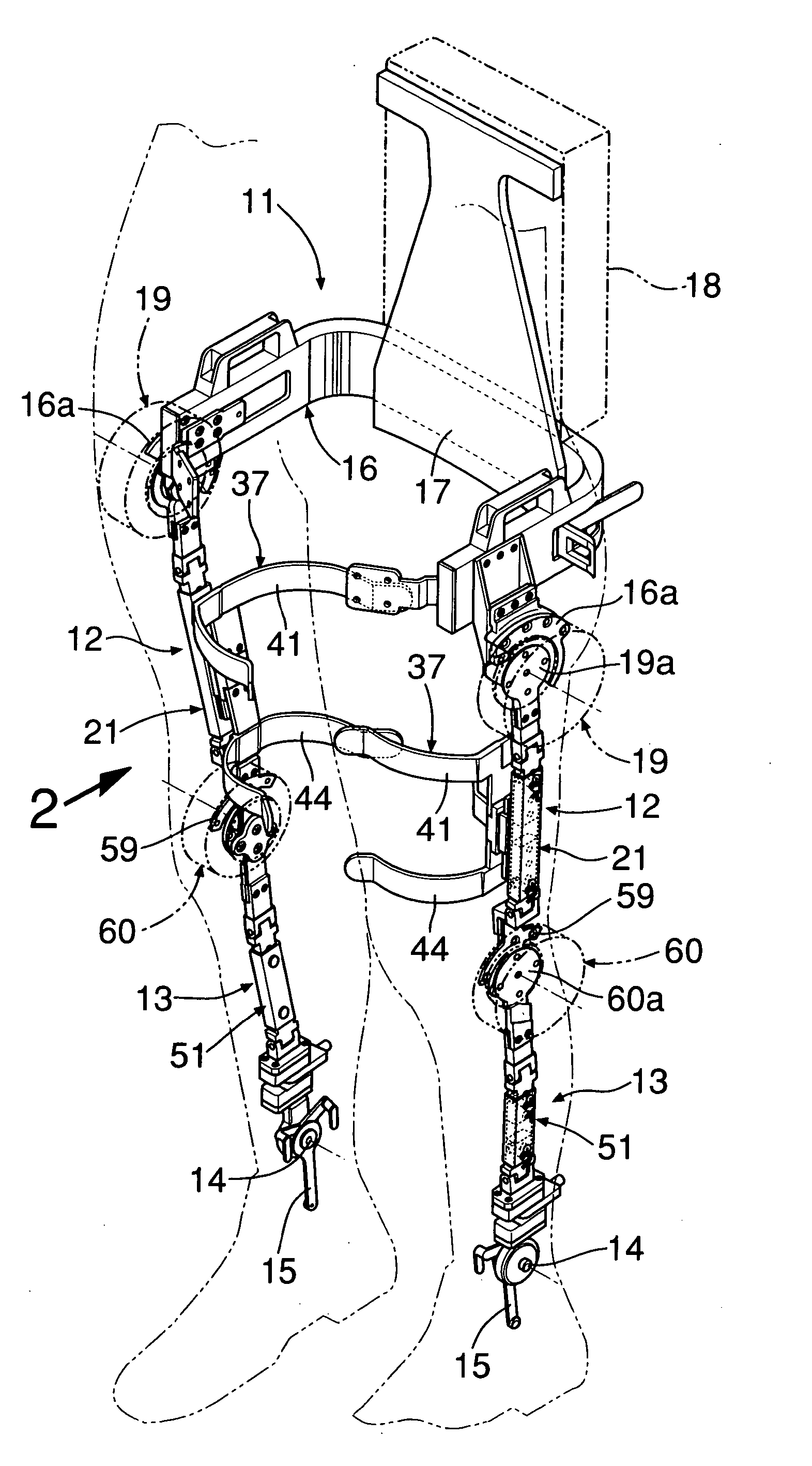
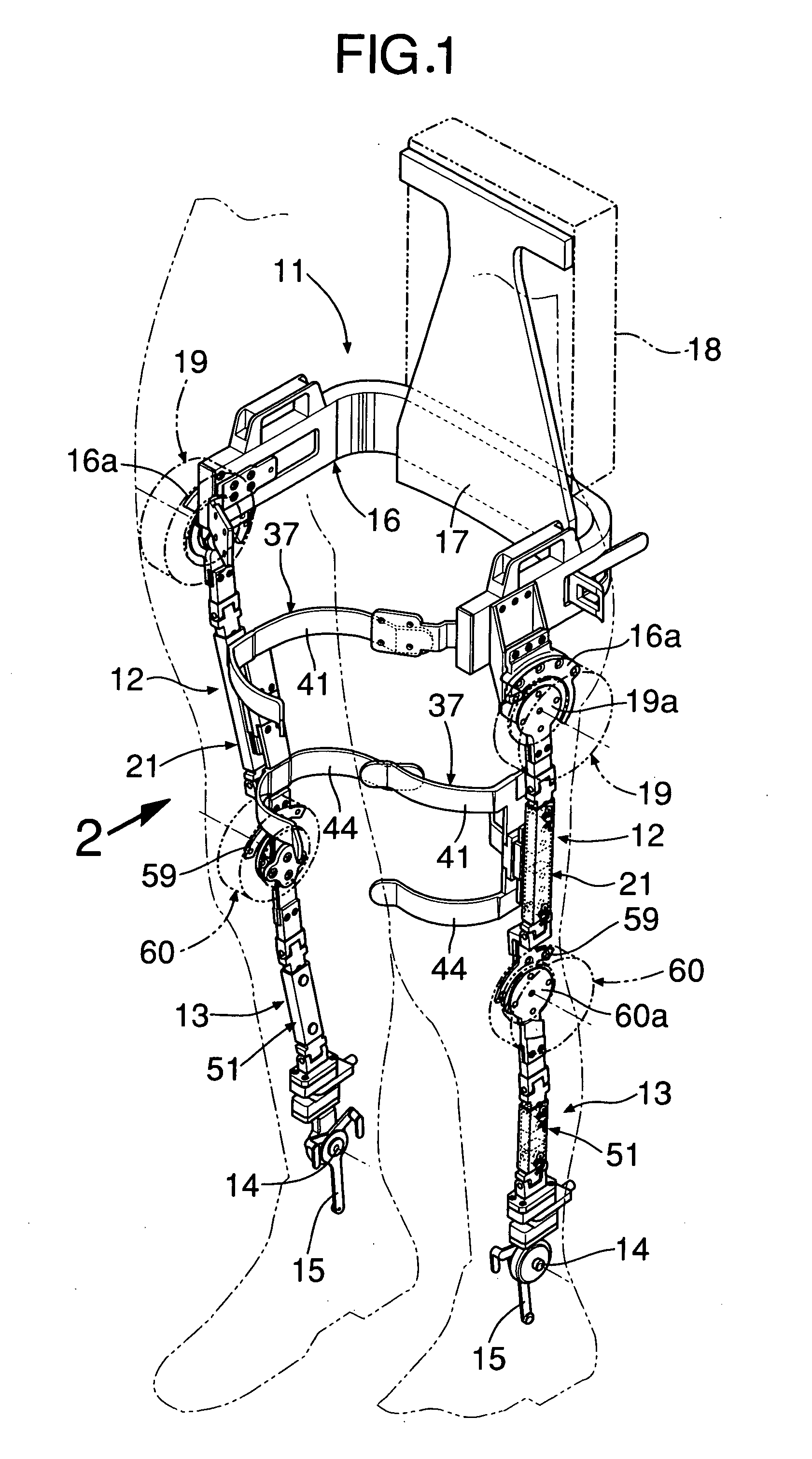
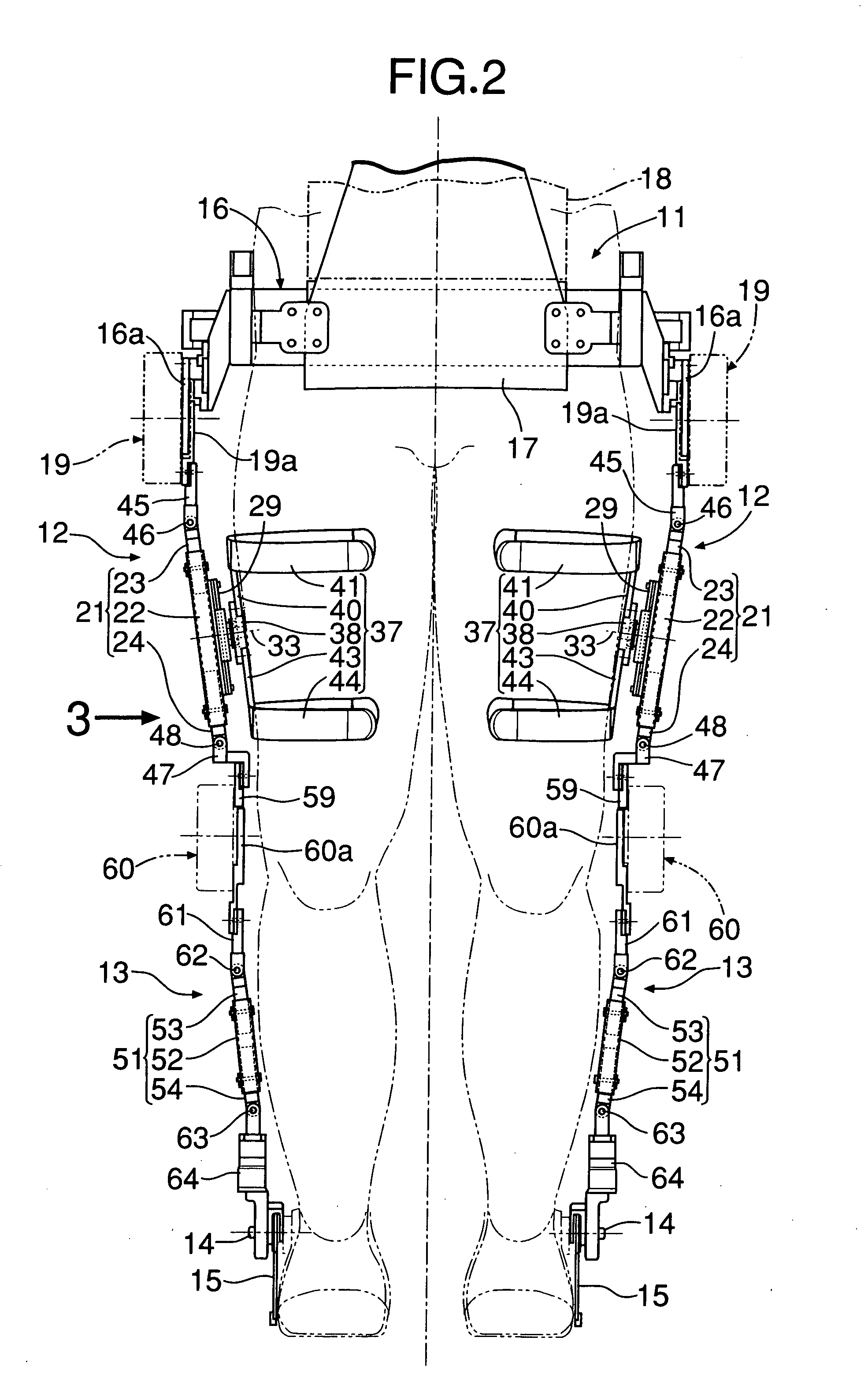
[0062] As shown in FIG. 1 to FIG. 3, a walking assistance system is attached to a user's left and right legs for assisting walking and is formed from a hip fitting 11 attached so as to surround left and right side parts and a rear part of the user's hip, left and right upper leg fittings 12 pivotably supported at left and right ends of the hip fitting 11 so that they can swing in the fore-and-aft direction and are attached along outer side faces of the user's left and right upper legs. Left and right lower leg fittings 13 are pivotably supported on lower ends of the left and right upper leg fittings 12 so that they can swing in the fore-and-aft direction and are attached along outer side faces of the user's left and right lower legs. Foot frames 15 are pivotably supported at lower ends of the lower leg fittings 13 via fulcrum pins 14 extending in the left-and-right direction so that they can swing in th...

second embodiment

[0081] the present invention is now described by reference to FIG. 7 and FIG. 8.

[0082] In the second embodiment, an upper leg fitting 12 has a different structure from that of the first embodiment, but other structures are the same as those of the first embodiment. In an explanation of the second embodiment, members corresponding to the members of the first embodiment are denoted by the same reference numerals and symbols as those of the first embodiment, and duplication of the explanation is therefore omitted.

[0083] An upper leg frame 21 of the upper leg fitting 12 of the second embodiment is formed from a lower frame 71 which is a pipe having a rectangular cross-section. An upper frame 72 is slidably fitted into the upper end of the lower frame 71. Opposite ends of a hydraulic cylinder 73 are connected by pins 74 and 75 to a pair of brackets 71a and 72a that project on side faces of the lower frame 71 and the upper frame 72. When the hydraulic cylinder 73 is expanded or contracte...

third embodiment

[0101] The operation of the third embodiment having the above-mentioned arrangement is now described.

[0102] While a user is equipped with the walking assistance system when the hip joint actuators 19 are operated, the left and right upper leg fittings 12 swing alternately in the fore-and-aft direction relative to the hip fitting 11 in a predetermined cycle. When the knee joint actuators 51 are operated, the left and right lower leg fittings 13 swing alternately in the fore-and-aft direction relative to the upper leg fittings 12 in a predetermined cycle, thus assisting the user to walk.

[0103] When the lower leg is kicked up towards the rear relative to the upper leg by bending the knee joint by means of the knee joint actuator 51 and the driving force transmission mechanism 52, if the knee joint actuator 51 fixed to the upper leg frame 21 so as to rotate the rotor 51b is driven, the center L2 of the lower leg side gear 62 moves in an arc shape around the center of the upper leg side...


PUM


Abstract

A walking assistance system includes an upper leg fitting which is attached along a user's upper leg. The upper leg fitting is formed from an upper leg frame that forms a framework of the upper leg fitting, and an upper leg coupling member that is vertically slidably supported on a guide rail provided on the upper leg frame, rotatably supported around a support shaft, and joined to the upper leg. When the upper leg fitting is made to swing in the fore-and-aft direction relative to the user's hip by a hip joint actuator, the position of the center of swing of the upper end of the upper leg fitting and the position of the hip joint are displaced, but it is possible to make the upper leg coupling member follow the upper leg by moving the upper leg coupling member relative to the upper leg frame, thus eliminating any uncomfortable sensation.

Description

CROSS-REFERENCE TO RELATED APPLICATIONS [0001] The present application claims priority under 35 USC 119 to Japanese Patent Application Nos. 2004-273319, filed on Sep. 21, 2004, 2004-273320, filed on Sep. 21, 2004 and 2004-305110, filed on Oct. 20, 2004, the entire contents of which are hereby incorporated by reference. BACKGROUND OF INVENTION [0002] 1. Field of the Invention [0003] The present invention relates to a walking assistance system that assists walking by permitting a user's upper leg swing in the fore-and-aft direction around a hip joint by means of a hip joint actuator and permits a user's lower leg swing in the fore-and-aft direction around a knee joint by means of a knee joint actuator. [0004] The present invention also relates to a walking assistance system that assists walking by permitting a user's lower leg swing in the fore-and-aft direction around a knee joint by means of a knee joint actuator. [0005] 2. Description of the Related Art [0006] Japanese Patent Appli...

Claims


Application Information

Patent Timeline
IPC IPC(8): A61F5/00
CPCA61F5/0102A61F2005/0139A61F2005/0137A61H1/0255A61H3/00A61H2201/0192A61H2201/14A61H2201/1628A61H2201/164A61H2201/1645A61H2201/165A61H2201/1676
Inventor SHIMADA, KEINODA, TATSUYA
Owner HONDA MOTOR CO LTD
Why Eureka
Try Eureka