Bracket for an orthodontic device

a technology for brackets and orthodontic devices, applied in the field of brackets for orthodontic devices, can solve the problems of hardly being able to completely treat larger tooth misalignments, hardly being able to unintentionally remove arch wires, and hardly being able to cause large teeth movements, etc., to achieve simple bracket configuration, reduce risk, and increase wear comfort

Inactive Publication Date: 2019-03-28
ELIDENT GMBH
View PDF0 Cites 14 Cited by
  • Summary
  • Abstract
  • Description
  • Claims
  • Application Information

AI Technical Summary

Benefits of technology

[0036]If can be particular advantageous when the bracket slot is defined at a side surface by the locking device and defined at the opposite side surface by the bracket base, It is appreciated that the bracket slot has to have a plurality of walls as a matter of principle wherein the walls define a space for receiving a respective arch wire. At least one of the walls should be formed by the locking device so that the wall can be released by a movement of the locking device in order to either insert an arch wire into the respective bracket slot or to remove the arch wire again. Thus, it has proven advantageous for a particularly simple configuration of the bracket according to the invention when at least one wall of the bracket slot is directly formed by the bracket base, this means the wall is not used for connecting the bracket overall with a respective tooth but already acts as part of the bracket slot. The locking device can envelop in this embodiment so to speak only a portion about the bracket base, wherein the bracket base and the locking device jointly form a free cross section which eventually forms the bracket slot.
[0037]It is a particular advantage of this embodiment that a thickness of the bracket measured perpendicular to a respective tooth surface can be rather small in spite of the camber. In particular it is not necessary to arrange a separate bracket slot on an entire bracket base. The smaller dimensions of the bracket according to the invention contribute in particular to increased wear comfort and to a smaller risk that the respective bracket separates from the tooth surface accidentally through chewing forces or similar. The suitability of brackets thus configured as an attachment is maintained since the bracket protrudes significantly beyond the surface of the respective tooth with the camber of the bracket. A corresponding embodiment of the bracket is evident from the subsequent embodiments.
[0038]In a particularly advantageous embodiment of the bracket according to the invention the bracket base transitions directly into the locking device. Thus, advantageously a transition from the bracket base to the locking device is configured by a bar whose cross section at a thickest location is 50% at the most, advantageously 40% at the most, further advantageously at least 30% at the most of a height that is measured parallel to the vertical axis of the bracket. Put differently the bar has a rather small cross section compared to the remaining bracket. This is particularly advantageous with respect to an elastic deformability of the locking device since the bracket has reduced stiffness in a portion of the bar. This has the consequence that the bracket is movable or deformable relative to the bracket base so that the insertion opening for the arch wire or the bracket slot can be expanded and eventually released .
[0039]In an advantageous embodiment of the bracket according to the invention the bracket base includes at least one fill-in portion where the attach

Problems solved by technology

Thus, it is hardly possible to unintentionally remove an arch wire that is inserted into the bracket slot wherein the removal from the bracket slot is attempted in a direction that is oriented perpendicular to an orientation of the bracket slot.
Known brackets have the particular disadvantage in the course of a combined orthodontic treatment that initially uses a clas

Method used


Image

  • Bracket for an orthodontic device
  • Bracket for an orthodontic device
  • Bracket for an orthodontic device

Examples


Embodiment Construction

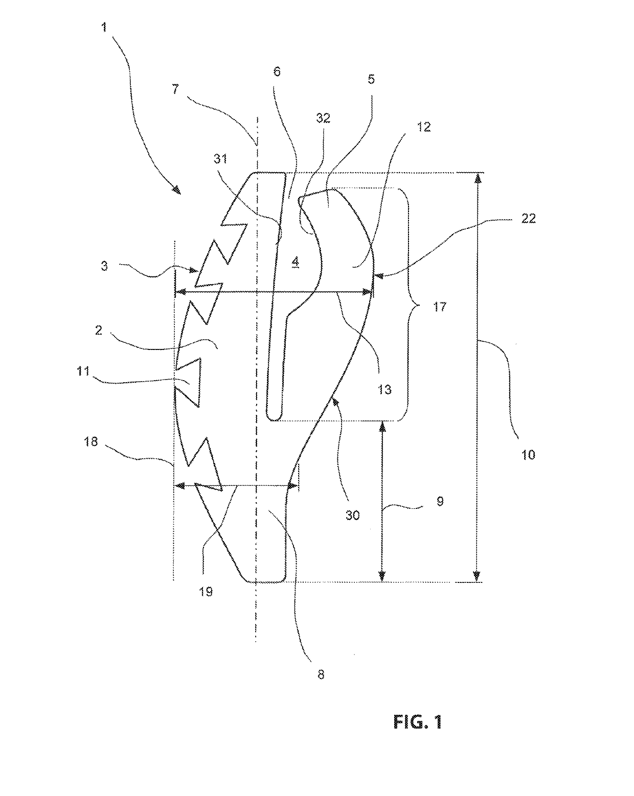
[0076]A first embodiment that is illustrated in FIG. 1 includes a bracket 1 according to the invention that includes a bracket base 2 and a locking device 5. The bracket base 2 and the locking device 5 are directly connected with each other by a bar 8. The bracket 1 includes an attachment surface 3 at a surface 28 of a tooth 27 that is not illustrated in FIG. 1 wherein the attachment surface is connected with the respective surface 28 in an inserted condition of the bracket 1 at least indirectly, advantageously directly.

[0077]In order to provide a better interconnection between the bracket 1 and the respective surface 28 of the respective tooth 27 the bracket base 2 includes a plurality of undercuts in a portion oriented towards the surface 28 wherein the undercuts are configured dovetailed in the illustrated embodiment. These undercuts respectively form a filling portion 11 that is configured to receive an attachment medium by which the bracket 1 is attached at the respective tooth...


PUM

PropertyMeasurementUnit
Lengthaaaaaaaaaa
Lengthaaaaaaaaaa
Lengthaaaaaaaaaa

Abstract

A bracket, for an orthodontic device, the bracket including a bracket base including an attachment surface configured to attach the bracket at an associated surface of a tooth; at least one bracket slot configured to receive at least one arch wire of the orthodontic device, wherein the bracket slot is arranged on a side of the bracket base that is oriented away from the attachment surface; and at least one locking device that is configured to lock at least the bracket slot at least partially so that the arch wire is prevented from moving out of the bracket slot, wherein the bracket is integrally formed in one piece, wherein the bracket is configured with a convex camber at a back side that is oriented away from the attachment surface, wherein the convex camber extends over at least 50% of a height of the bracket that is measured parallel to the vertical axis of the bracket.

Description

RELATED APPLICATIONS[0001]This application is a continuation of International application PCT / EP 2017 / 063217 filed on May 31, 2017, claiming priority from German patent application DE 10 2016 110 161.3, filed on Jun. 2, 2016, both of which are incorporated in their entirely by this reference.FIELD OF THE INVENTION[0002]The instant application relates to a bracket for an orthodontic device, the bracket comprising: a bracket base including an attachment surface for attaching the bracket at an associated surface of a tooth; at least one bracket slot for receiving at least one arch wire of the orthodontic device, wherein the bracket slot is arranged on a side of the bracket base that is oriented away from the attachment surface; and at least one locking device that is configured to lock at least the bracket slot at least partially so that the arch wire is prevented from moving out of the bracket slot, wherein the bracket is integrally formed in one piece.[0003]The instant application al...

Claims


Application Information

Patent Timeline
IPC IPC(8): A61C7/28
CPCA61C7/28A61C7/20A61C7/002A61C7/145A61C7/148A61C7/30A61C13/0013A61C2201/007A61C13/0019
Inventor JO, YONG-MIN
Owner ELIDENT GMBH
Why Eureka
Try Eureka