Method and device for detecting a rotational speed, especially the rotational speed of the wheel of a vehicle

Inactive Publication Date: 2006-03-23
LUCAS AUTOMOTIVE GMBH
View PDF4 Cites 2 Cited by
  • Summary
  • Abstract
  • Description
  • Claims
  • Application Information

AI Technical Summary

Benefits of technology

[0006] An object of the present invention is to provide a method and an apparatus of the initially described type, with wh

Problems solved by technology

It has however emerged that during operation of a motor vehicle the rotational speed measurement may be adversely affected by various disturbing influences.
For example, an unwanted series resistance in the sensor line, short circuits or components of impaired function may lead to a displacement of the signal level of the output signal.
As a result of this, the decoding electronics are no longer able to identify the signal level

Method used


Image

  • Method and device for detecting a rotational speed, especially the rotational speed of the wheel of a vehicle
  • Method and device for detecting a rotational speed, especially the rotational speed of the wheel of a vehicle
  • Method and device for detecting a rotational speed, especially the rotational speed of the wheel of a vehicle

Examples


Embodiment Construction

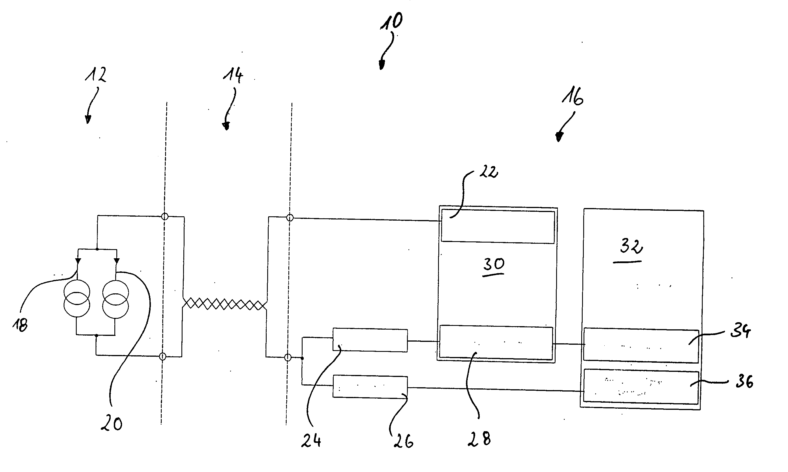
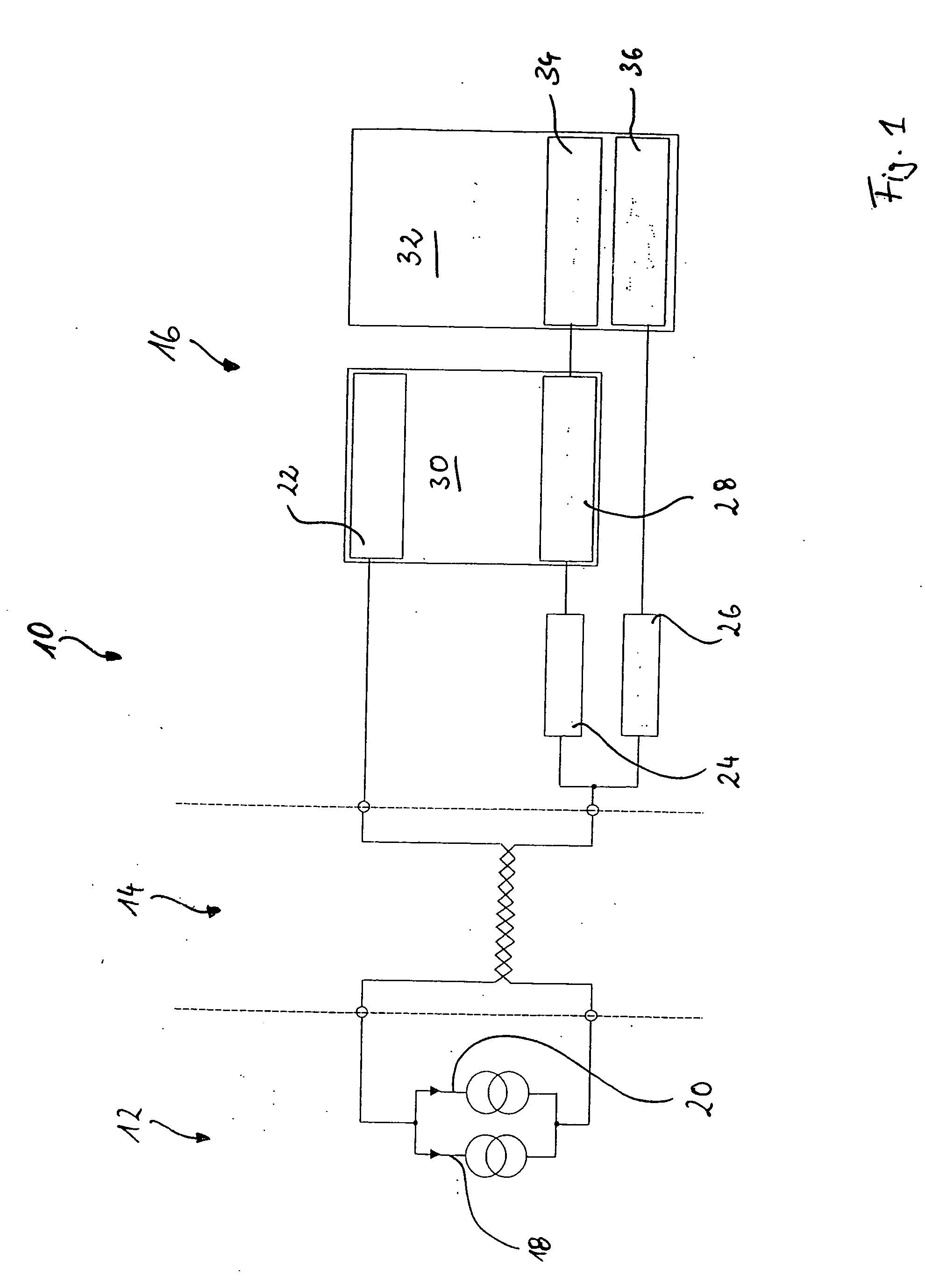
[0027] In FIG. 1 an apparatus according to the invention is generally denoted by 10. It comprises a wheel speed sensor 12, wiring 14 and a signal processing unit 16.

[0028] The vehicle sensor 12 comprises two signal paths, namely a signal path 18 that delivers a “high” current of e.g. 14 mA when the sensor 12 detects a specific event, e.g. an inductive excitation, and the signal path 20 that delivers a “low” current of e.g. 7 mA when the sensor 12 is in its idle state. The wheel speed sensor 12 is connected by the wiring 14 to the signal processing unit 16. The signal processing unit comprises a power supply unit 22 for the wheel speed sensor 12, a first low-pass filter 24 and a second low-pass filter 26. The signal processing unit 10 further comprises an evaluation device 28, which interrogates specific properties of the output signal of the wheel speed sensor 12 obtained by the low-pass filter 24. More details about this will be provided below.

[0029] The power supply unit 22 for ...


PUM


Abstract

The invention relates to a method and an apparatus for measuring a rotational speed, in particular a rotational speed of a wheel of a motor vehicle, by means of a speed sensor, wherein the speed sensor produces an output signal characterizing the actual rotational speed and wherein the output signal of the speed sensor is sampled and further processed in accordance with sampled values thus obtained. For an—in hardware terms—simple realization, according to the invention it is provided that the output signal is sampled at a predetermined sampling rate over at least one measuring cycle, that in each case the amplitude of sampled values obtained in the measuring cycle is determined and that from the rate of occurrence of sampled values of an amplitude lying within a predetermined amplitude range at least one signal level occurring during the measuring cycle in the output signal is determined.

Description

CROSS REFERENCE TO RELATED APPLICATIONS [0001] This application is a continuation of International Application No. PCT / EP2004 / 002523 filed Mar. 11, 2004, the disclosures of which are incorporated herein by reference, and which claimed priority to German Patent Application No. 103 12 208.7 filed Mar. 19, 2003, the disclosures of which are incorporated herein by reference.BACKGROUND OF THE INVENTION [0002] The present invention relates to a method according to the preamble of claim 1 and to an apparatus according to the preamble of claim 15. [0003] Such methods and apparatuses are known from the background art. For control of recently designed brake systems or traction control systems that is tuned to the actual vehicle operating state, the rotational speed of individual wheels of a motor vehicle has to be monitored permanently with sufficiently high precision. For this purpose, speed sensors of various designs, such as for example inductive sensors, Hall sensors or the like, are used...

Claims


Application Information

Patent Timeline
IPC IPC(8): G01B5/30B60T8/171B60T8/88G01P3/489
CPCB60T8/171G01P3/489B60T2270/416B60T8/885
Inventor GOEBEL, EUGENFUSS, MANFREDALFTER, INGO
Owner LUCAS AUTOMOTIVE GMBH
Why Eureka
Try Eureka