Electric power source apparatus using fuel cell and method of controlling the same

a technology of electric power source and fuel cell, which is applied in the manufacture of secondary cells, electrochemical generators, emergency power supply arrangements, etc., can solve the problems of low output density of fuel cells, increased electric power consumption of portable electronic devices, and critical charging tim

Inactive Publication Date: 2006-03-30
HITACHI LTD
View PDF20 Cites 175 Cited by
  • Summary
  • Abstract
  • Description
  • Claims
  • Application Information

AI Technical Summary

Problems solved by technology

Therefore, there is a tendency that the electric power consumption of the portable electronic devices will increase further.
In order to realize an electric power source with a long continuous service time by secondary batteries, the charging time is a critical issue.
Although fuel cells have volume energy density (WH / L) and weight energy density (Wh / kg) superior to conventional secondary batteries in high density, output density of the fuel cell is low.
However, because of low output density of the fuel cell it is very difficult to realize downsizing and lightweight of the electric power source apparatus when the fuel cell is mounted on the external battery charger for the mobile device.
On the other hand, although the fuel cells can be made small-sized and lightweight but have a small generation area and a small output power, the fuel cells used as an exterior battery charger that requires a guaranteed power of the AC adapter for conventional devices are difficult to employ; the system can be applied to devices that are designed not to require an electric power larger than a certain value, which lacks reality.

Method used


Image

  • Electric power source apparatus using fuel cell and method of controlling the same
  • Electric power source apparatus using fuel cell and method of controlling the same
  • Electric power source apparatus using fuel cell and method of controlling the same

Examples


embodiment 1

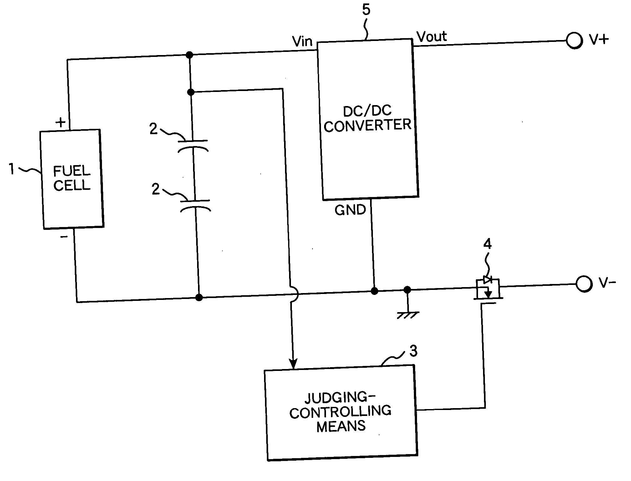
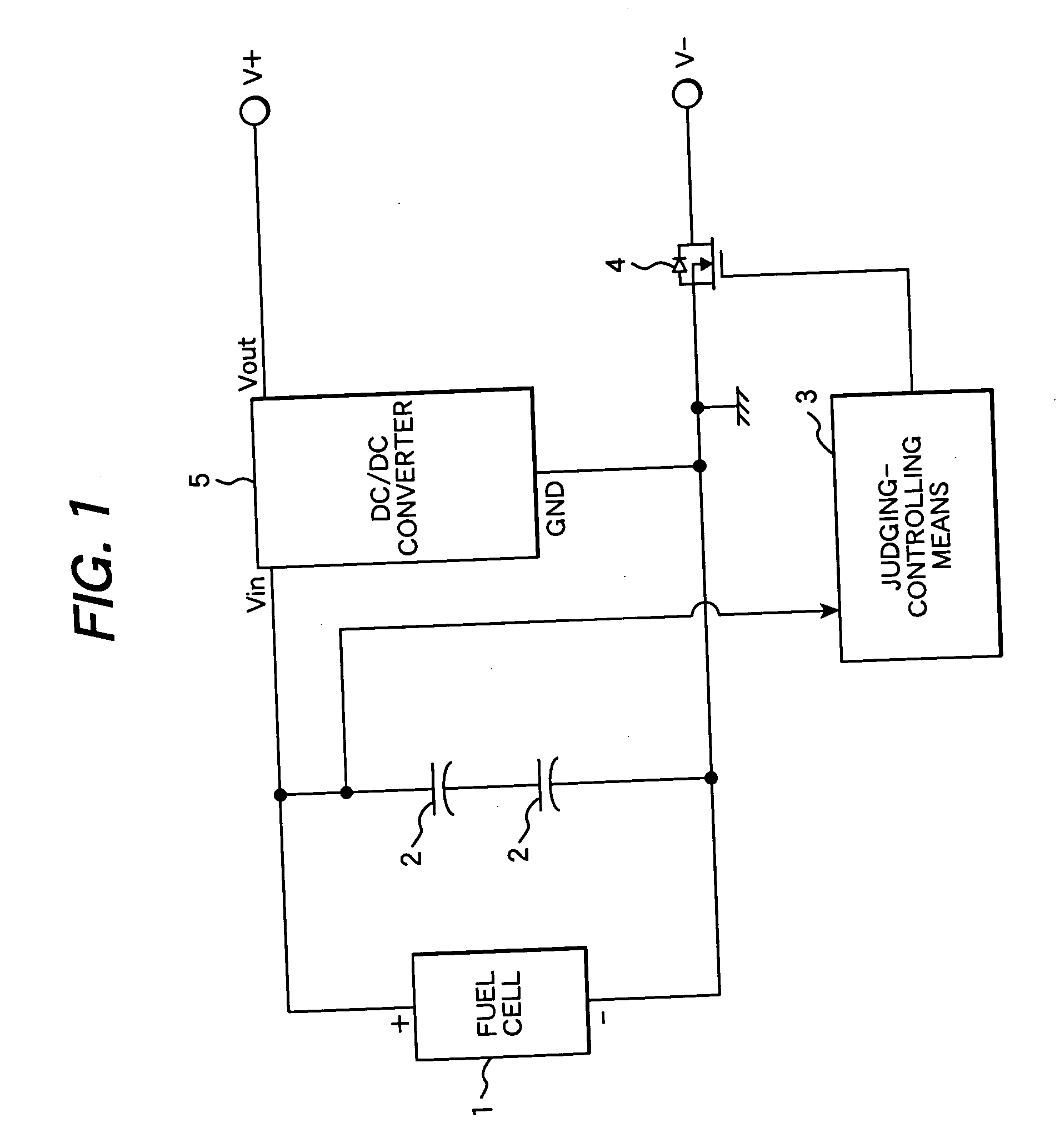
[0035] The embodiment 1 will be explained by reference to FIGS. 1 to 9. FIG. 1 is a block diagram showing a construction of the electric power source apparatus, and connections of power lines and signal lines. In this embodiment the number of fuel cells is set so that the maximum voltage of the fuel cell does not exceed the withstanding voltage of the electric double layer condenser.

[0036] In this embodiment the circuit has a fuel cell 1, which is used as a high energy density power source, and an electric double layer condenser (EDLC) 2, which is used as a high power density power source. The EDLC can be substituted by another secondary battery that generates a necessary power. In order to simplify the construction of the circuit, a direct methanol fuel cell (DMFC) is preferable for the fuel cell 1.

[0037] Although two EDLCs 2 are used in FIG. 1, the number of EDLC should be such that the maximum voltage calculated from the number of series fuel cells required for outputting elect...

embodiment 2

[0052] Embodiment 2 will be explained by reference to FIGS. 10 and 11. FIG. 10 is a block diagram of a circuit construction of the electric power source apparatus and connections of power lines and signal lines.

[0053] In case where a load on the fuel cell 1 is zero and the voltage becomes almost the natural potential, the voltage increases abruptly. In this embodiment, the system is provided with a function for cutting over-voltage to prevent damage of EDLC 2, which is caused by application of the over-voltage due to the increase of the voltage of the fuel cell 1 to the EDLC 2. As shown in FIG. 10, a constant voltage diode 21 is connected in parallel with the fuel cell thereby to cut a voltage applied to EDLC 2 to lower the voltage, which is lower than the withstanding voltage of EDLC 2. As shown in FIG. 11, the voltage higher than the preset voltage may be cut with a shunt regulator, or a resistor is connected in parallel with the fuel cell to realize the above mentioned function....

embodiment 3

[0056] Embodiment 3 will be explained by reference to FIGS. 12 to 14. FIG. 12 is a block diagram showing a construction of the electric power source apparatus and connections of power lines and signal lines.

[0057] In this embodiment, in addition to the embodiments, a power region of the fuel cell where charge from the fuel cell to EDLC becomes faster. That is, compared to embodiment 2, the electric power source apparatus is so designed that a quantity of current that the fuel cell can output in the upper limit preset voltage of EDLC becomes larger.

[0058] Comparisons of design ranges among embodiments 1 to 3 are shown in FIG. 13. The cell structure of the fuel cell and EDLC is changed in embodiment 3; the number of the fuel cells per one cell of EDLC is larger than that in embodiment 2. Accordingly, in the cell construction of this embodiment, there is an increased danger that voltage of the electric power source apparatus exceeds the withstanding voltage of the EDLC because the el...


PUM

PropertyMeasurementUnit
cell voltageaaaaaaaaaa
voltageaaaaaaaaaa
voltageaaaaaaaaaa

Abstract

A method of controlling an electric power source apparatus, which comprises supplying electric power to an electronic device on which a secondary battery is mounted from a power source apparatus having a fuel cell and an auxiliary power source. Electric power is supplied intermittently to a charging terminal of the electronic device by means of a switch for controlling conduction and interruption of an output terminal of the power source apparatus.

Description

CLAIM OF PRIORITY [0001] This application claims priority from Japanese application Serial No. 2004-287617, filed on Sep. 30, 2004, the content of which is hereby incorporated by reference into this application. DESCRIPTION OF THE INVENTION [0002] 1. Field of the Invention [0003] The present invention relates to an electric power source apparatus using a fuel cell and a method of controlling the apparatus. [0004] 2. Related Art [0005] As a result of recent development in electronic technologies, rapid popularization of mobile phones, notebook personal computers (hereinafter referred to as notebook PC), audio-visual apparatuses or mobile terminal devices is going on. These portable devices are driven by secondary batteries. New type of secondary batteries appeared; they were downsized and made high-energy density. The batteries have changed from seal-lead batteries, Ni / Cd batteries, Ni hydrogen batteries to Li ion batteries. In any batteries, development of active materials and high ...

Claims


Application Information

Patent Timeline
Patent Type & Authority Applications(United States)
IPC IPC(8): H01M8/00
CPCH01M8/04365Y02E60/50H01M8/04388H01M8/04544H01M8/04626H01M8/04955H01M10/0436H01M10/46H01M16/006H01M2250/30H02J7/0052H02J7/34H02J2001/004Y02B90/18H01M8/0438H02J2300/30Y02B90/10Y02E60/10H02J7/00
Inventor NORIMATSU, YASUAKIKANOUDA, AKIHIKOKIKUCHI, MUTSUMI
Owner HITACHI LTD
Why Eureka
Try Eureka