Power management for a self-powered device scheduling a dynamic process
What is Al technical title?
Al technical title is built by PatSnap Al team. It summarizes the technical point description of the patent document.
a self-powered device and dynamic process technology, applied in the field of control and automation, can solve the problems of large power consumption of rapid expansion networks, waste of power communication with other networked computing devices, and current self-powered devices
Active Publication Date: 2018-01-23
INVENT LY LLC
View PDF2 Cites 121 Cited by
Summary
Abstract
Description
Claims
Application Information
AI Technical Summary
This helps you quickly interpret patents by identifying the three key elements:
Problems solved by technology
Method used
Benefits of technology
Problems solved by technology
These rapidly expanding networks consume a tremendous amount of power, which is typically supplied from traditional electrical power grids.
However, current self-powered devices, such as devices that obtain energy from solar power, typically waste much of their power communicating with other networked computing devices.
Such an installed base of sensors creates issues such as powering such sensors as well as transporting and storing the data received from the sensors.
Such conventional approaches are unlikely to be sufficient with the grand vision of the “Internet of Things”.
The communications bandwidth (and data storage on the Internet to implement such an approach) could include hundreds of times as many sensors as conventional smartphones, potentially consuming the highest amount of energy of the Internet.
If scaled to a trillion sensors, a huge number of devices would need to be implemented with batteries that would be unaffordable (or at least inconvenient) to change.
A huge amount of traffic on already congested networks would further increase the power needs of each device, since higher antenna output would likely be needed to overcome interference and noise.
Method used
Image
Click on the blue label to locate the original text in one second.
Reading with bidirectional positioning of images and text.
Examples
Embodiment Construction
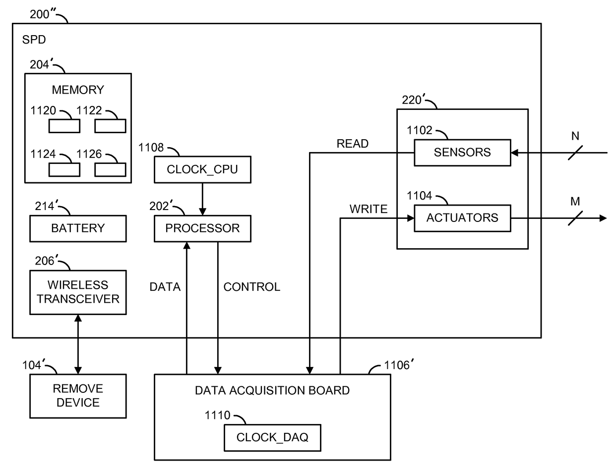
[0045]Embodiments of self-powered systems, devices, and methods are described herein. The self-powered system may include a computing device that selectively communicates with a self-powered device. The self-powered device may include: a circuit to power the self-powered device; memory; a processor; and a program mechanism that is stored in the memory for execution by the processor. The program mechanism may include instructions for selecting one of a plurality of modes of operation, including a first mode of operation in which the self-powered device consumes less than a pre-determined amount of power and a second mode of operation in which self-powered device consumes more than the pre-determined amount of power. (See FIG. 20).
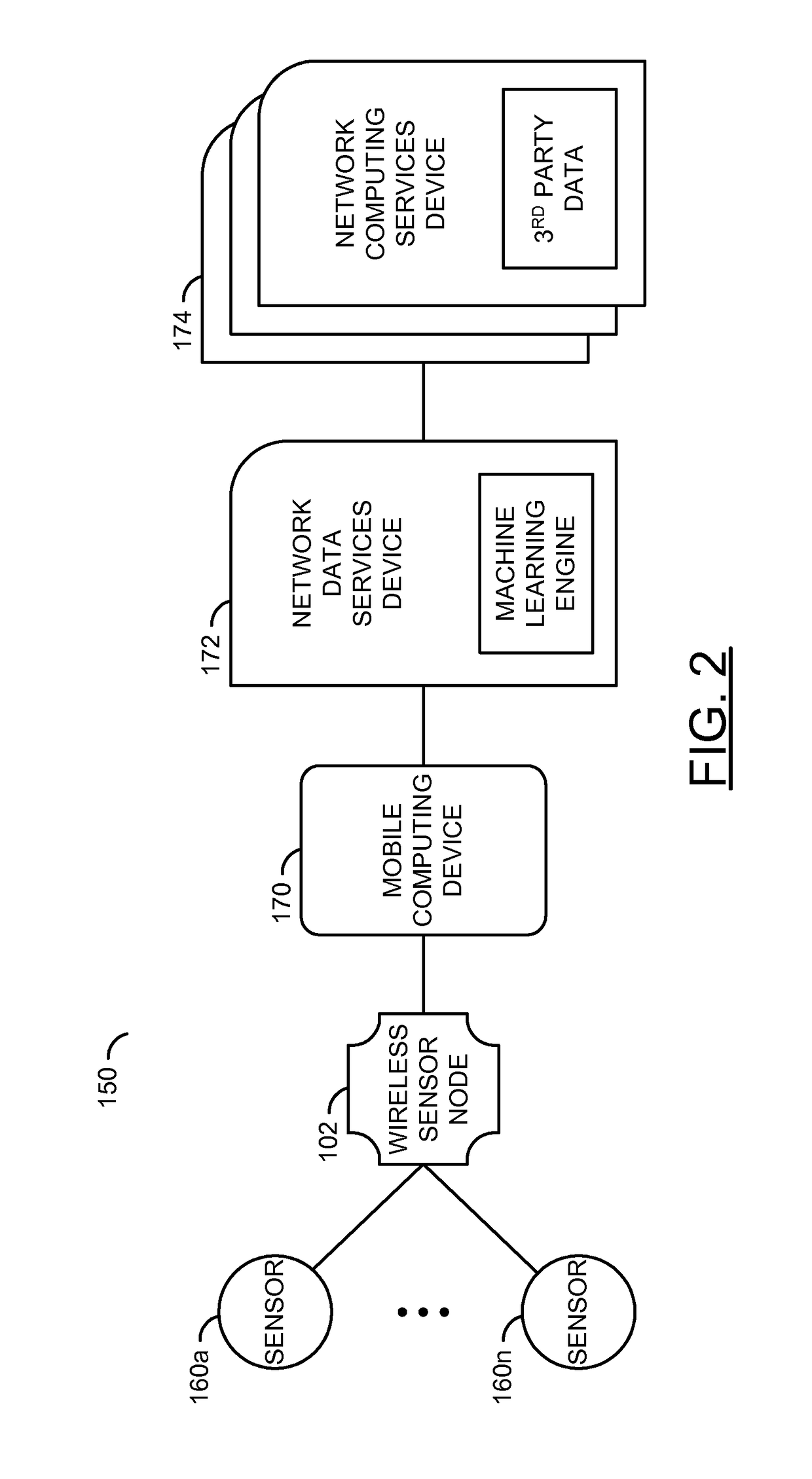
[0046]Embodiments of the invention provide a context-aware and / or power-aware wireless sensor network system that enables application needs to determine which data is captured, transmitted and / or stored at the edge of the wireless sensor network. Such an imp...
PUM
Abstract
A device comprising a battery, a memory, a data acquisition circuit and a processor. The sensors may sample a current state of a dynamic process. The data acquisition circuit may have a first clock rate based on a sampling rate of the dynamic process. The data acquisition circuit may read sensor information from the sensors. The processor may have a second clock rate. The processor may process the sensor information and generate a monitoring signal based on at least one of the sensor information, a model of the dynamic process and a desired state of the dynamic process. The processor may schedule procedures for the device and determine computation times for the procedures based on context information. The second clock rate is faster than the first clock rate. The procedures are scheduled based on the sampling rate, the computation times for the procedures and opportunities to enter a standby mode to conserve power.
Description
[0001]This application relates to U.S. Ser. No. 14 / 169,464, filed Jan. 31, 2014, which relates to U.S. Ser. No. 14 / 103,209, filed Dec. 11, 2013, which relates to U.S. Ser. No. 13 / 946,414, filed Jul. 19, 2013, now U.S. Pat. No. 8,850,242, which relates to U.S. Ser. No. 13 / 406,469, filed Feb. 27, 2012, now U.S. Pat. No. 8,516,279, which relates to U.S. Ser. No. 12 / 472,327, filed May 26, 2009, now U.S. Pat. No. 8,127,158, which relates to U.S. Ser. No. 11 / 443,668, filed May 30, 2006, now U.S. Pat. No. 7,539,882, which relates to U.S. Provisional Application No. 60 / 685,976, filed May 30, 2005. This application also relates to U.S. Ser. No. 14 / 090,099, filed Nov. 26, 2013. Each of the mentioned applications are hereby incorporated by reference in their entirety.FIELD OF THE INVENTION[0002]The embodiments disclosed herein relate to control and automation, optimal control, computer science, embedded systems, data analysis and power management in self-powered electronic devices, and, in par...
Claims
Application Information
Patent Timeline
Application Date:The date an application was filed.
Publication Date:The date a patent or application was officially published.
First Publication Date:The earliest publication date of a patent with the same application number.
Issue Date:Publication date of the patent grant document.
PCT Entry Date:The Entry date of PCT National Phase.
Estimated Expiry Date:The statutory expiry date of a patent right according to the Patent Law, and it is the longest term of protection that the patent right can achieve without the termination of the patent right due to other reasons(Term extension factor has been taken into account ).
Invalid Date:Actual expiry date is based on effective date or publication date of legal transaction data of invalid patent.