LCD device reducing asymmetry in the leakage light

a liquid crystal display and leakage light technology, applied in non-linear optics, instruments, optics, etc., can solve the problems of insufficient improvement in the symmetry of the leakage light achieved in the splay-oriented mode lcd device, degrade the overall reduce the image quality of the lcd device, so as to reduce the asymmetry of the leakage light and suppress the leakage light , the effect of improving the image quality

Active Publication Date: 2006-04-06
BEIHAI HKC OPTOELECTRONICS TECH CO LTD
View PDF2 Cites 15 Cited by
  • Summary
  • Abstract
  • Description
  • Claims
  • Application Information

AI Technical Summary

Benefits of technology

[0015] In view of the above problem in the conventional LCD device, it is an object of the present invention to provide an LCD device which is capable of suppressing the leakage light, and also reducing the asymmetry of the leakage light upon display of a black color, to thereby improve the image quality of the LCD device.
[0022] In the LCD device of the first aspect of the present invention, since the slow axis and the another axis in the thickness direction are rotated by the positive rotational angle θs with respect to the fast axis or the Y-axis, the difference in the retardation caused by the pre-tilt angle of the LC molecules between the top side and the bottom side can be reduced, thereby reducing the asymmetry in the viewing angle characteristic.
[0029] In the LCD device of the second aspect of the present invention, the pre-tilt angle of the LC molecules on the first substrate is different from the pre-tilt angle on the second substrate. Thus, assuming that the LC molecules existing from the first substrate to the second substrate are overlapped on a single plane, the optical elastic axis of the LC layer is deviated from the direction of the Z-axis by an angle corresponding to the difference between the positive pre-tilt angle and the negative pre-tile angle. This reduces the difference of the retardation between the top side and the bottom side, thereby reducing the asymmetry in the viewing angle characteristic.
[0030] In accordance with the LCD device of the present invention, the specific configuration of the optical compensation film reduces the difference of the retardation caused by the pre-tile angle of the LC layer between the top side and the bottom side. Thus, the asymmetry in the viewing angle characteristic can be reduced, thereby improving the contrast-to-viewing angle characteristic of the LCT) device.

Problems solved by technology

As a result, the luminance upon display of a black color is asymmetric between the top-side view and the bottom-side view, as shown in FIGS. 17 and 18, which degrades the overall image quality of the LCD device.
That is, the reduction of the leakage light rather degrades the image quality of the LCD device based on the viewing angle dependency of the luminance of the leakage light.
Thus, the improvement in the symmetry of the leakage light achieved in the splay-oriented mode LCD device is not sufficient, and it is required to further improve the image quality in the splay-oriented mode LCD device.

Method used


Image

  • LCD device reducing asymmetry in the leakage light
  • LCD device reducing asymmetry in the leakage light
  • LCD device reducing asymmetry in the leakage light

Examples


Embodiment Construction

[0053] Now, the present invention is more specifically described with reference to accompanying drawings, wherein similar constituent elements are designated by similar or related reference numerals throughout the drawings.

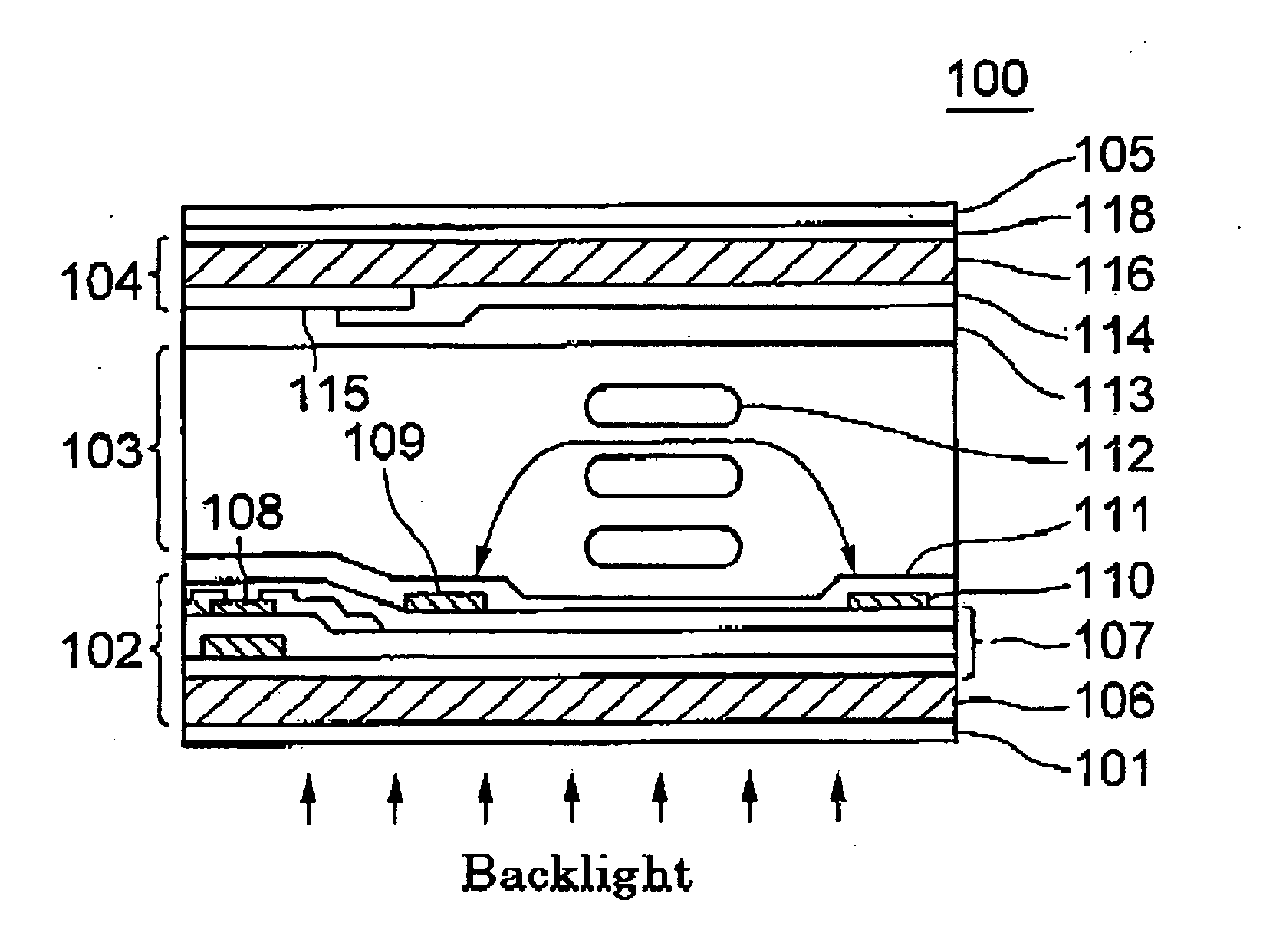
[0054]FIG. 1 shows an LCD device according to a first embodiment of the present invention. The LCD device, generally designated by numeral 100, is implemented as an IPS mode LCD device, and includes a light-incident-side (first) polarizing film 101, a TFT substrate 102, an orientation film 111, an LC layer 103, an orientation film 113, a CF substrate 104, an optical compensation film 118, and a light-emitting-side (second) polarizing film 105, which are arranged in this order as viewed from a backlight unit (not shown) toward the front side of the LCD device.

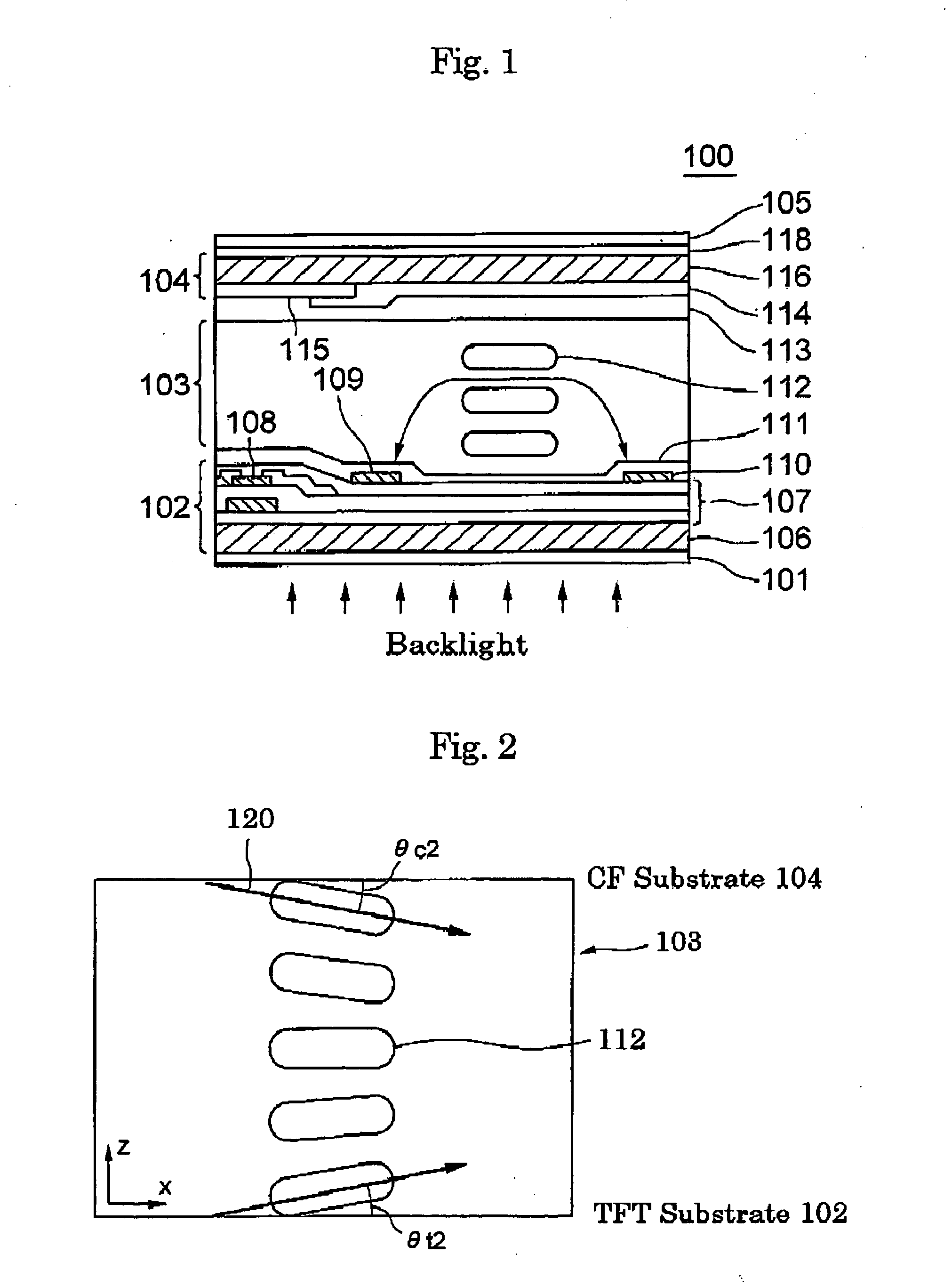
[0055] The LC layer 103 includes therein splay-oriented LC molecules 112 having a twisted angle of about zero degree. FIG. 2 shows the orientations of the longer optical axes 120 of the LC molecules 112 in t...


PUM

PropertyMeasurementUnit
twisted angleaaaaaaaaaa
angleaaaaaaaaaa
azimuth angleaaaaaaaaaa

Abstract

An LCD device includes therein a splay-oriented LC layer, first and second substrates sandwiching therebetween the LC layer, and an optical compensation film for reducing leakage light upon display of a black color. The optical compensation film has three optical elastic axes including a fast axis coinciding the Y-axis, a slow axis rotated from the X-axis by a positive rotational angle θ1, and another axis rotated from the Z-axis by the positive rotational angle θ1. The positive rotational direction coincides with a counter-clockwise direction within the substrate surface, as viewed from minus side toward the positive side of the Y-axis.

Description

BACKGROUND OF THE INVENTION [0001] (a) Field of the Invention [0002] The present invention relates to a liquid crystal display (LCD) device and, more particularly, to an in-plane-switching (IPS) mode LCD device, which is capable of reducing asymmetry in the leakage light on the screen of the LCD device. [0003] (b) Description of the Related Art [0004] In general, an in-plane-switching (IPS) mode LCD device includes a liquid crystal (LC) layer, a pair of substrates sandwiching therebetween the LC layer, and a pair of polarizing films each attached is with a corresponding one of the substrates on the outer side thereof. In the IPS mode LCD device, the initial orientation of the LC molecules in the LC layer is determined so that the screen of the LCD device represents a black color when no voltage is applied onto the LC layer, and so that the screen represents a white color when a specific voltage is applied onto the LC layer to thereby turn the orientation of the LC molecules therein ...

Claims


Application Information

Patent Timeline
Patent Type & Authority Applications(United States)
IPC IPC(8): G02F1/1335
CPCG02F1/133632G02F1/134363G02F2001/133773G02F1/133773
Inventor NAGAI, HIROSHIIKENO, HIDENORI
Owner BEIHAI HKC OPTOELECTRONICS TECH CO LTD
Why Eureka
Try Eureka