
Systems and methods for low power clock generation

a low-power clock and clock generation technology, applied in the direction of instruments, burglar alarm mechanical actuation, sustainable buildings, etc., can solve the problems of reducing the accuracy and thus the effectiveness of identification tags, and achieve the effect of reducing the asymmetry of charge injection and reducing the error source in the duty cycle correction circui

Active Publication Date: 2009-09-08
TEXAS INSTR INC
View PDF5 Cites 11 Cited by
  • Summary
  • Abstract
  • Description
  • Claims
  • Application Information

AI Technical Summary

Benefits of technology

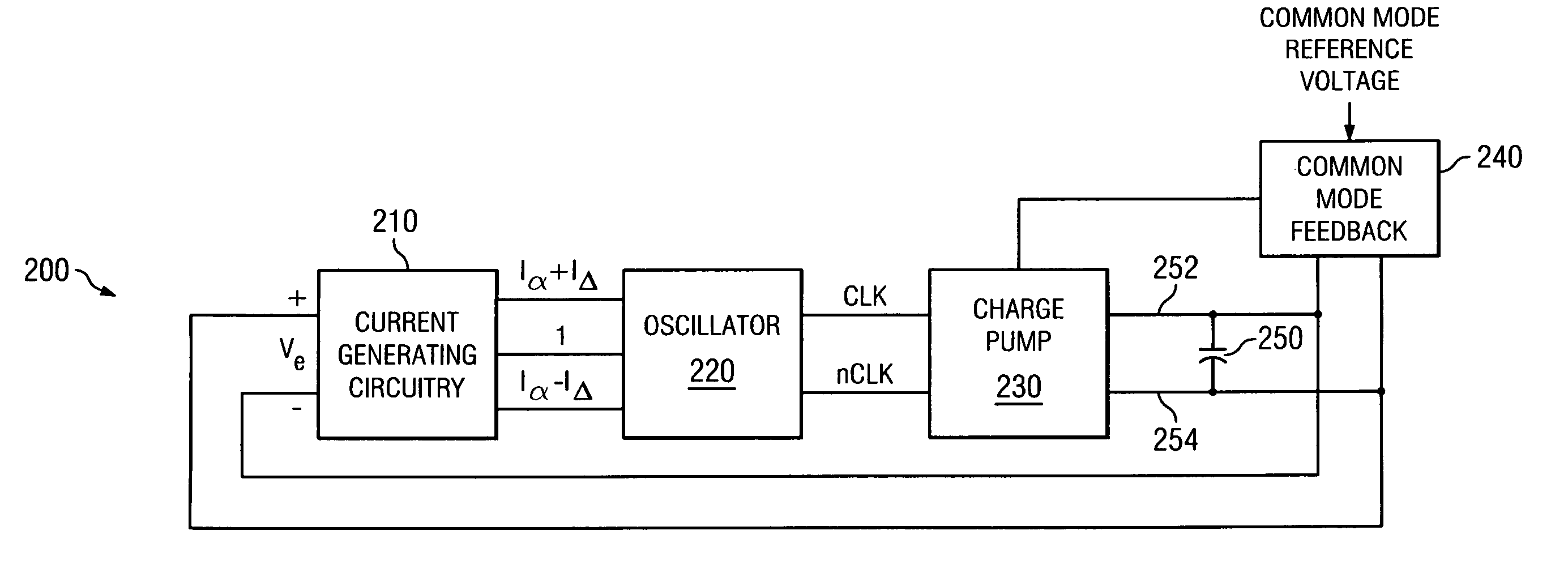
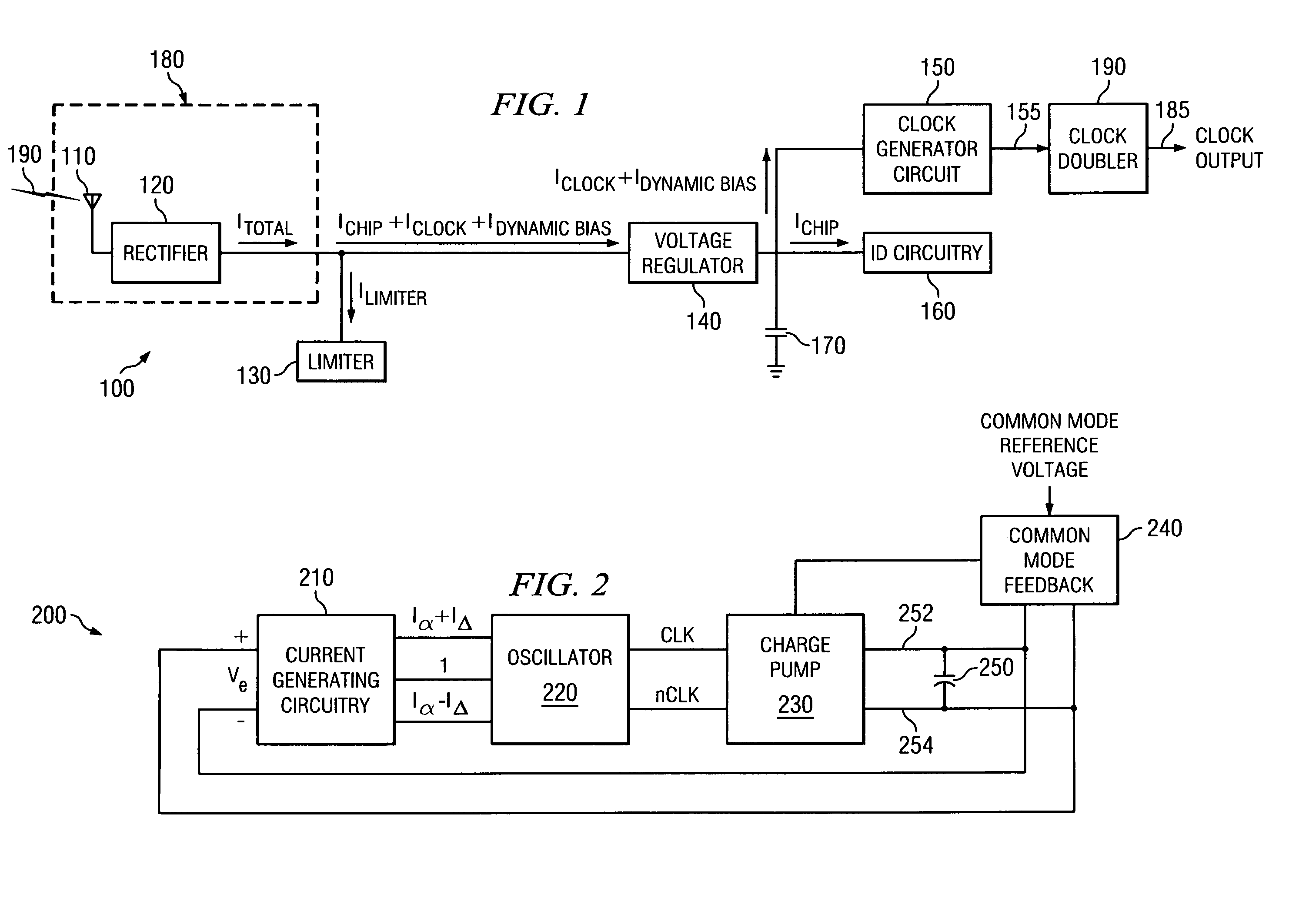
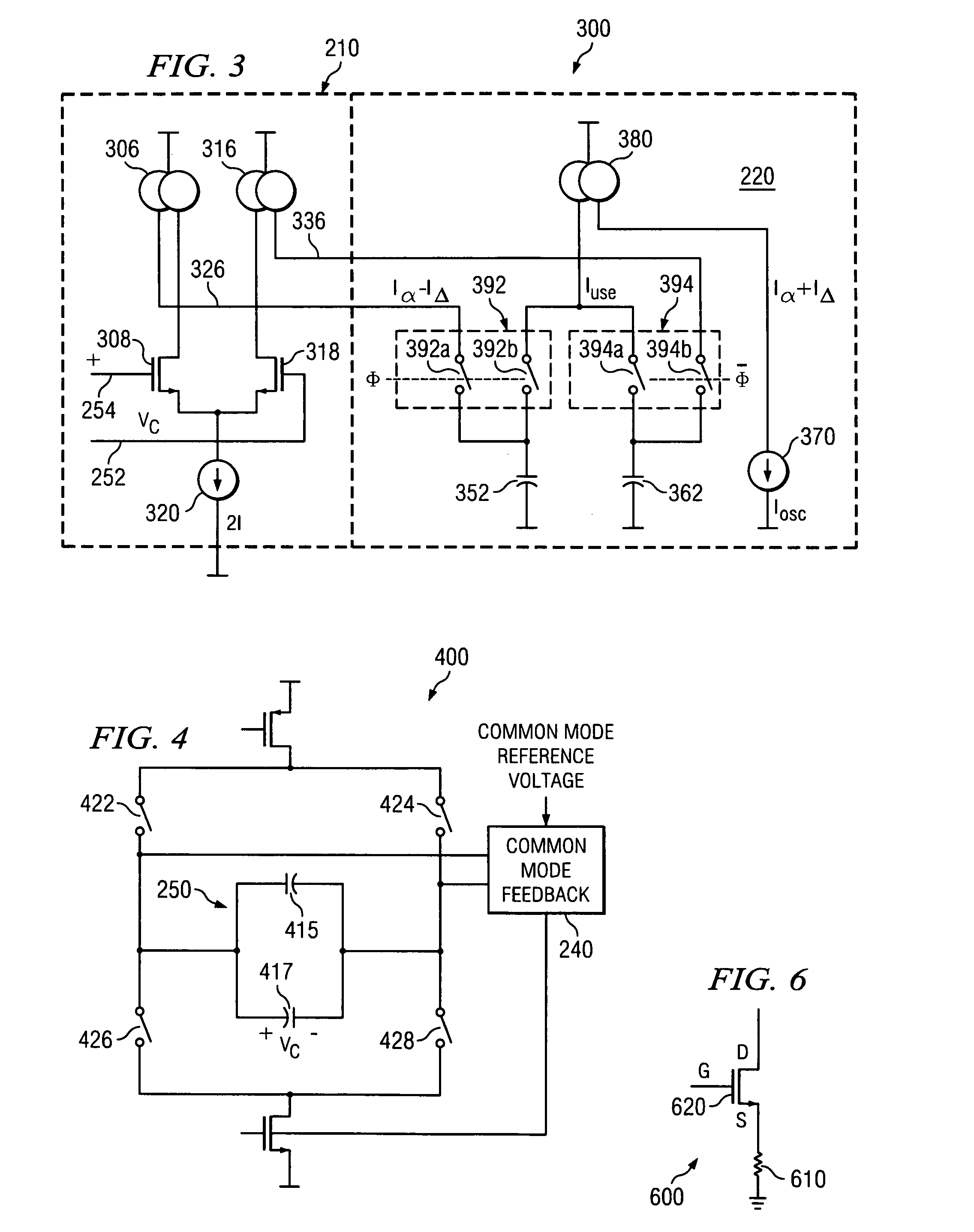
The present invention provides systems and methods for improving clock accuracy in low power environments. The invention includes a radio frequency energy receiver, a first clock generator with a duty cycle correction circuit, and a second clock generator with a positive going clock edge for each edge of the first clock. The second clock generator includes an oscillator, a charge pump, a capacitor, and a current generating circuit. The invention also includes a dynamic bias circuit for reducing asymmetry of charge injection at the output of the charge pump. The invention also provides low power frequency doubles that include a first clock generator and a second clock generator with a positive going clock edge for each edge of the first clock. The technical effects of the invention include improved clock accuracy and reduced power consumption.

Problems solved by technology

Such an approach, however, may also reduce the accuracy and thus effectiveness of the identification tag.

Method used


Image

  • Systems and methods for low power clock generation
  • Systems and methods for low power clock generation
  • Systems and methods for low power clock generation

Examples


Embodiment Construction

[0019]The present invention is generally related to systems and methods for improving clock accuracy, and more particularly to systems and methods for increasing clock accuracy in a low power environment.

[0020]Some embodiments of the present invention provide radio frequency devices that include a radio frequency energy receiver. The radio frequency energy receiver is operable to receive a radio frequency energy and to convert the radio frequency energy to a DC current. In addition, the devices further include a first clock generator that generates a first clock at a first frequency and second clock generator that generates another clock based on the first clock. The first clock generator includes a duty cycle correction circuit. The second clock has a positive going clock edge for each edge of the first clock. As used herein, the term “clock” is used in its broadest sense to mean any signal whether it be electrical, optical or otherwise that exhibits a particular frequency or range...


PUM


Abstract

Various systems and methods for low power identification are described herein. For example, a radio frequency device including a radio frequency energy receiver. The radio frequency energy receiver is operable to receive a radio frequency energy and to convert the radio frequency energy to a DC current. In addition, the device further includes a first clock generator that generates a first clock at a first frequency and second clock generator that generates another clock based on the first clock. The first clock generator includes a duty cycle correction circuit. The second clock has a positive going clock edge for each edge of the first clock.

Description

BACKGROUND OF THE INVENTION[0001]The present invention is generally related to systems and methods for improving clock accuracy, and more particularly to systems and methods for increasing clock accuracy in a low power environment.[0002]Various devices exists that are remotely powered by radio frequency energy received from a transmitting device. As one example, radio frequency identification tags exist that are capable of accessing power transmitted via a radio frequency signal. In such an application, the equivalent Thevenin voltage received at the radio frequency identification tag may vary between one half Volt at a substantial distance from the transmitting device, and forty Volts when the transmitting device is very near the identification tag. To compensate for this substantial voltage difference, excess voltage may be dissipated through a circuit as simple as a resistor. Further, the voltage range over which such a tag is capable of operating may be increased by lowering the...

Claims


Application Information

Patent Timeline
Patent Type & Authority Patents(United States)
IPC IPC(8): H04B1/06H04B7/00
CPCG06F1/3203Y02B60/1217Y02D10/00
Inventor BALACHANDRAN, GANESH K.BARNETT, RAYMOND E.
Owner TEXAS INSTR INC
Learn More