Position measuring device, position measurement method, exposure apparatus, exposure method, and superposition measuring device and superposition measurement method

Inactive Publication Date: 2006-09-12
NIKON CORP
View PDF44 Cites 11 Cited by
  • Summary
  • Abstract
  • Description
  • Claims
  • Application Information

AI Technical Summary

Benefits of technology

[0030]Consequently, in a superposition measuring device and a superposition measurement method according to the present invention, when the superposition error is measured for a plural

Problems solved by technology

However, the conventional position measuring devices, position measurement methods and exposure apparatus described above suffer from the problems described below.
Exposure apparatus are typically provided with the aforementioned plurality of different types of sensors as part of the alignment system, but in all such systems, the influence of the marks and optical aberrations mean that the image obtained is asymmetric, leading to positional deviation errors, and a deterioration in the alignment precision.
However, in these measurement methods, there are associated manufacturing limits.
Furthermore, this method also suffers from a deterioration in the S/N ratio of the high frequency component, which incorporates surface roughness on the wafer as noise.
However, alignment devices using a LSA system or a FIA system are typically positioned inside the exposure apparatus in a confined space below the projection lens (in the vicinity of the wafe

Method used


Image

  • Position measuring device, position measurement method, exposure apparatus, exposure method, and superposition measuring device and superposition measurement method
  • Position measuring device, position measurement method, exposure apparatus, exposure method, and superposition measuring device and superposition measurement method
  • Position measuring device, position measurement method, exposure apparatus, exposure method, and superposition measuring device and superposition measurement method

Examples


Example

[0056]As follows is a description of embodiments of a position measuring device, a position measurement method, an exposure apparatus, and an exposure method of the present invention, with reference to FIG. 1 through FIG. 20F.

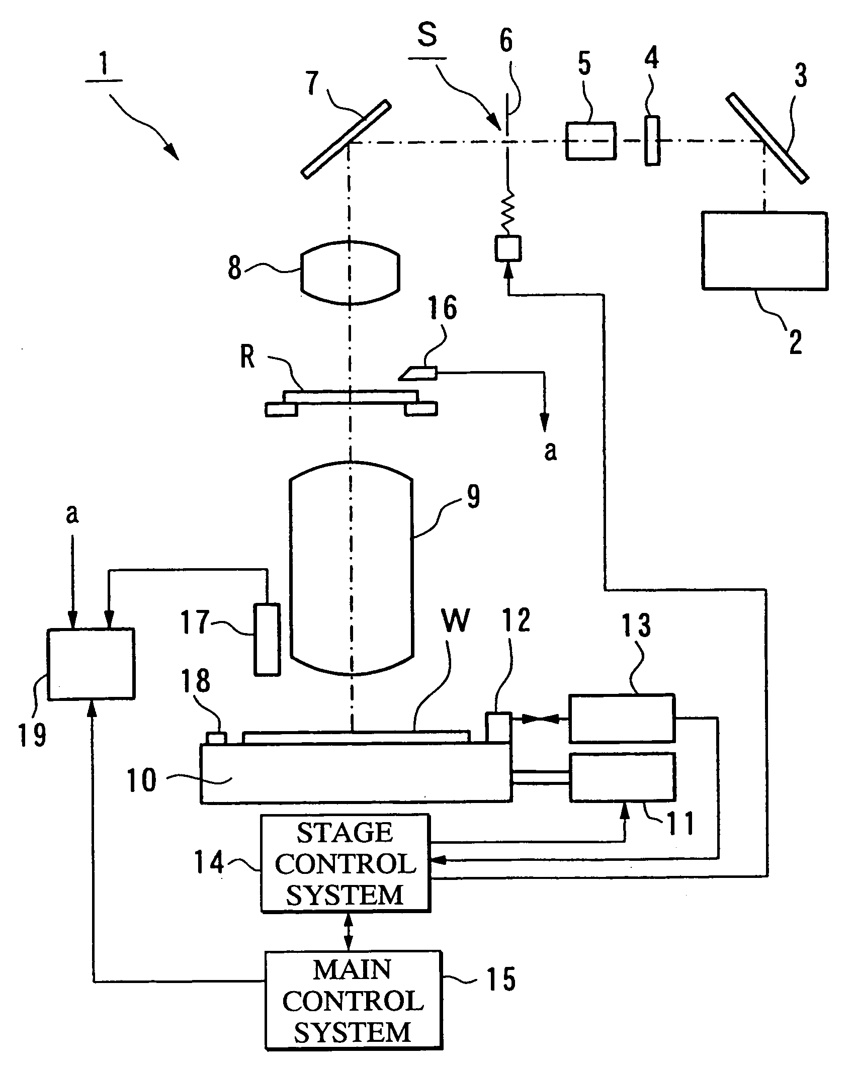
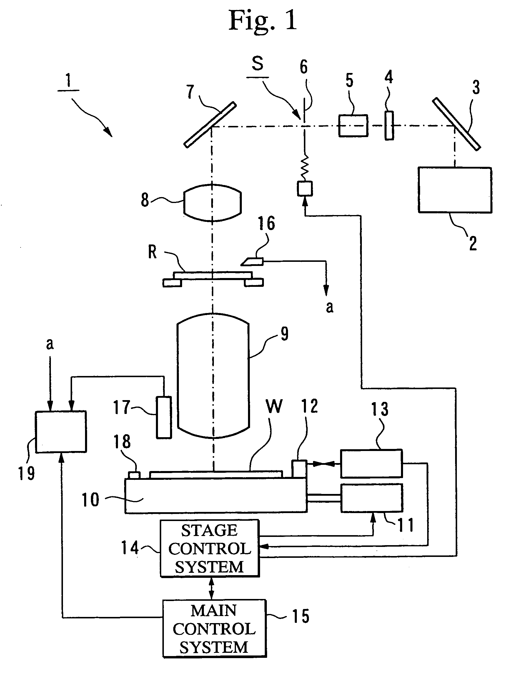
[0057]FIG. 1 is a schematic structural diagram of an exposure apparatus 1 of the present invention. Illuminating light emitted from a light source 2 such as an extra high pressure mercury lamp or a excimer laser is reflected off a reflective mirror 3 and enters a wavelength selecting filter 4 which transmits only light of the wavelength necessary for the exposure light beam. Having passed through the wavelength selecting filter 4, the illuminating light is adjusted by a fly eye integrator 5 to produce a light beam with a uniform intensity distribution, which then reaches a reticle blind 6. The reticle blind 6 is a device for altering the size of the aperture S, thereby setting the illumination area of the reticle (mask) R exposed to the illuminating light beam....


PUM


Abstract

This position measuring device comprising a calculation unit 19 calculates mark position information relating to the position of the mark by using a mark signal obtained by irradiating a detection beam onto the mark formed on an object W, and a correction device 19 for correcting the calculation results from the calculation unit 19 based on the asymmetry of the mark signal.
As a result, positional deviation resulting from asymmetry can be detected, and by correcting for this deviation the effect that the image asymmetry has on the measurement can be reduced. Therefore, a more accurate high precision alignment can be performed, and there is no requirement to increase the NA of the detection optical system, nor to prepare a special short wavelength light source, meaning increases in the size and cost of the apparatus can also be prevented.

Description

[0001]This is a Continuation of application Ser. No. 09 / 954,281 filed Sep. 18, 2001 now abandoned, which in turn is a Continuation of PCT / JP00 / 01760, filed Mar. 23, 2000. The entire disclosures of the prior applications are hereby incorporated by reference herein in their entirety.TECHNICAL FIELD[0002]The present invention relates to an exposure apparatus and an exposure method for projection exposure of a photomask pattern image onto a photosensitive substrate, and a position measuring device and a position measurement method for measuring the exposure position and the drawing accuracy of the aforementioned photomask, as well as to a superposition measuring device and a superposition measurement method for measuring the superposition error of the exposed pattern, all within a manufacturing process for a semiconductor element or a liquid crystal display element or the like.[0003]The present application is a continuation application of PCT / JP00 / 01760, and is based on Japanese Patent ...

Claims


Application Information

Patent Timeline
IPC IPC(8): G01C15/00G01C19/00G01C9/00G06F15/00G06F19/00G03F9/00
CPCG03F9/7092G03F9/7088G03F7/70775G03F7/7085G03F9/7003G03F9/7084
Inventor NAKAJIMA, SHINICHI
Owner NIKON CORP
Why Eureka
Try Eureka