

Friction stir welding method for reversely rotating stirring needle and shaft shoulder
A friction stir, welding method technology, applied in welding equipment, non-electric welding equipment, metal processing equipment, etc., can solve the asymmetry of joint performance, reduce the bearing capacity of welded structures, temperature field, joint structure and residual stress distribution asymmetry, etc. problems, to achieve the effect of improving mechanical properties, reducing asymmetry, and reducing torque effects
- Summary
- Abstract
- Description
- Claims
- Application Information
AI Technical Summary
Problems solved by technology
Method used
Image

Examples
specific Embodiment approach 1
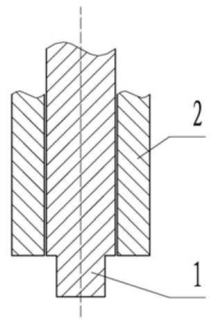
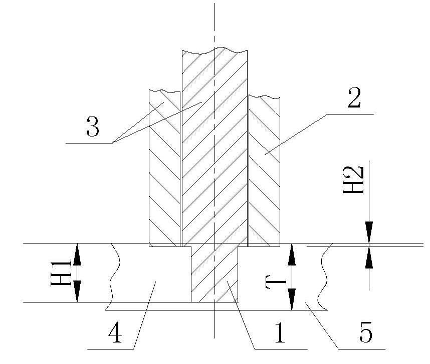
[0014] Specific implementation mode one: as Figure 1~3 As shown, the agitating needle and the shaft shoulder described in this embodiment
[0015] The friction stir welding method with reverse rotation is realized according to the following steps:
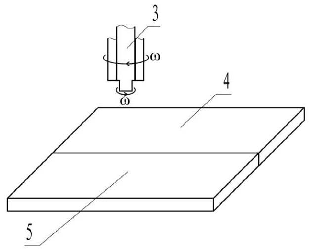
[0016] Step 1. Set the first workpiece 4 to be welded and the second workpiece 5 to be welded butt-connected and both are located on the same horizontal plane (that is, the first workpiece to be welded 4 and the second workpiece to be welded 5 are paired), and clamped on the On the workbench; the first workpiece to be welded 4 and the second workpiece to be welded 5 are plates;
[0017] Step 2, the stirring needle 1 of the stirring head 3 is rotated at a speed of 100 to 3000 rpm Plunge into the part to be welded (that is, the butt surface of the first workpiece to be welded 4 and the second workpiece to be welded 5); the rotation direction of the shaft shoulder 2 of the stirring head 3 is opposite to that of the stirring needle...
specific Embodiment approach 2
[0020] Specific embodiment two: In step two of this embodiment, the rotation speed of the stirring needle 1 It is 200~2500 rpm. The rotation speed of the shoulder can be selected according to the specific conditions of the first welded workpiece 4 and the second welded workpiece 5 , in order to reduce the resistance of the mixing head and the forward movement. Other steps are the same as in the first embodiment.
specific Embodiment approach 3
[0021] Specific embodiment three: In step two of this embodiment, the piercing speed of the stirring head 3 is 2-4 mm / min. The penetration speed of the stirring head 3 can be selected according to the specific conditions of the first workpiece 4 and the second workpiece 5 to be welded, so that the stirring head is easy to penetrate into the workpiece to be welded. Other steps are the same as those in Embodiment 1 or 2.
PUM
 Abstract
Description
Claims
Application Information