Telescopic shaft for motor vehicle steering

Inactive Publication Date: 2006-04-20
NSK LTD
View PDF3 Cites 25 Cited by
  • Summary
  • Abstract
  • Description
  • Claims
  • Application Information

AI Technical Summary

Benefits of technology

[0019] As described above, if the contact pressure between the spherical member and the axial groove is kept below 1500 MPa, even when the surface

Problems solved by technology

However, there is a case that abrasion of the nylon film advances with elapse of time of use and the backlash in the direction of rotation becomes great.
As a result, backlash in the direction of rotation may become great.
However, according to Japanese Patent Application Laid-Open No. 2001-50293 or German Patent DE No. 3730393C2 described above, since the spherical member is in point contact with a raceway surface of the axial groove of the female shaft or the male shaft, it is

Method used


Image

  • Telescopic shaft for motor vehicle steering
  • Telescopic shaft for motor vehicle steering
  • Telescopic shaft for motor vehicle steering

Examples


first embodiment

of the Telescopic Shaft

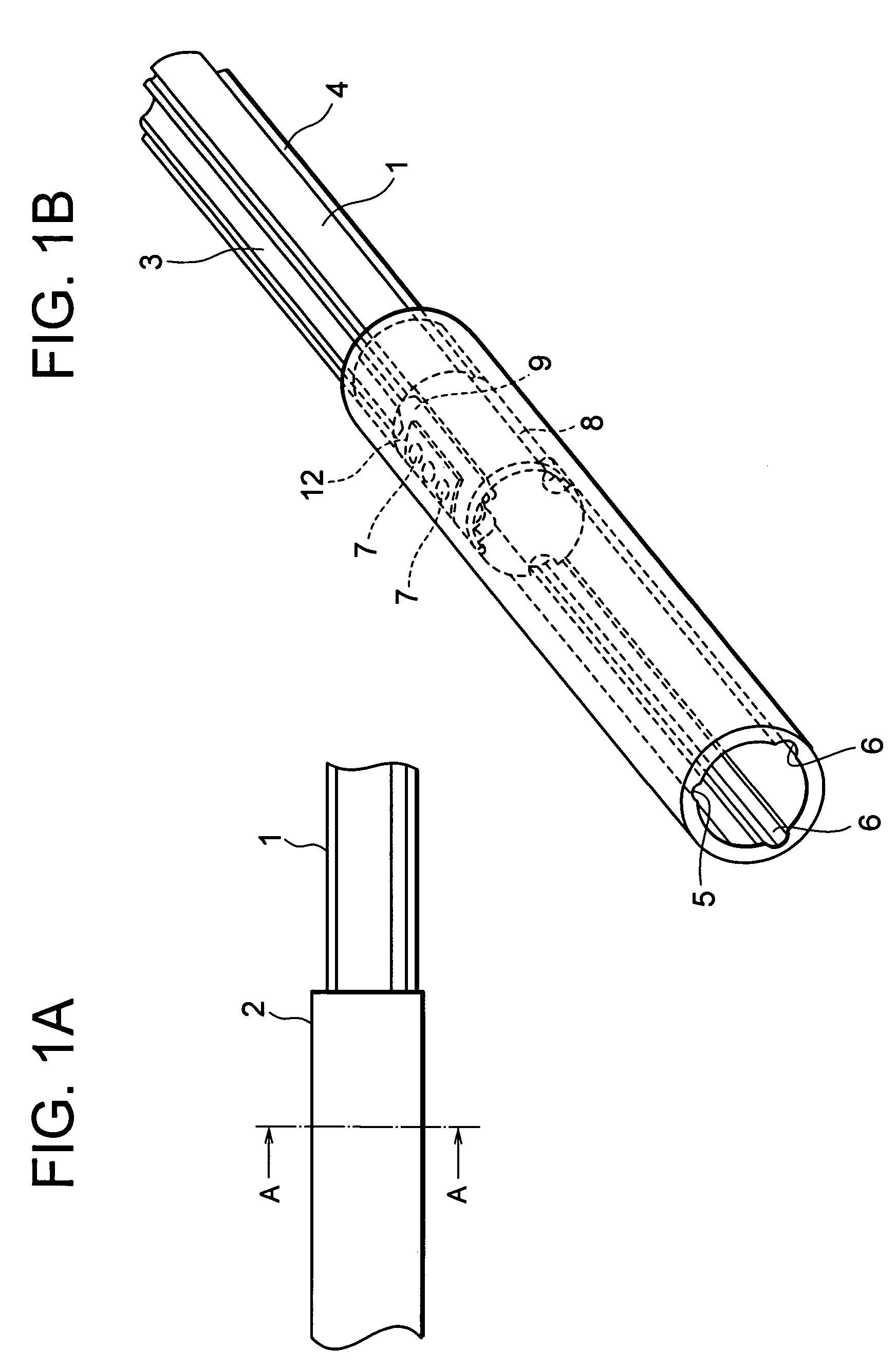
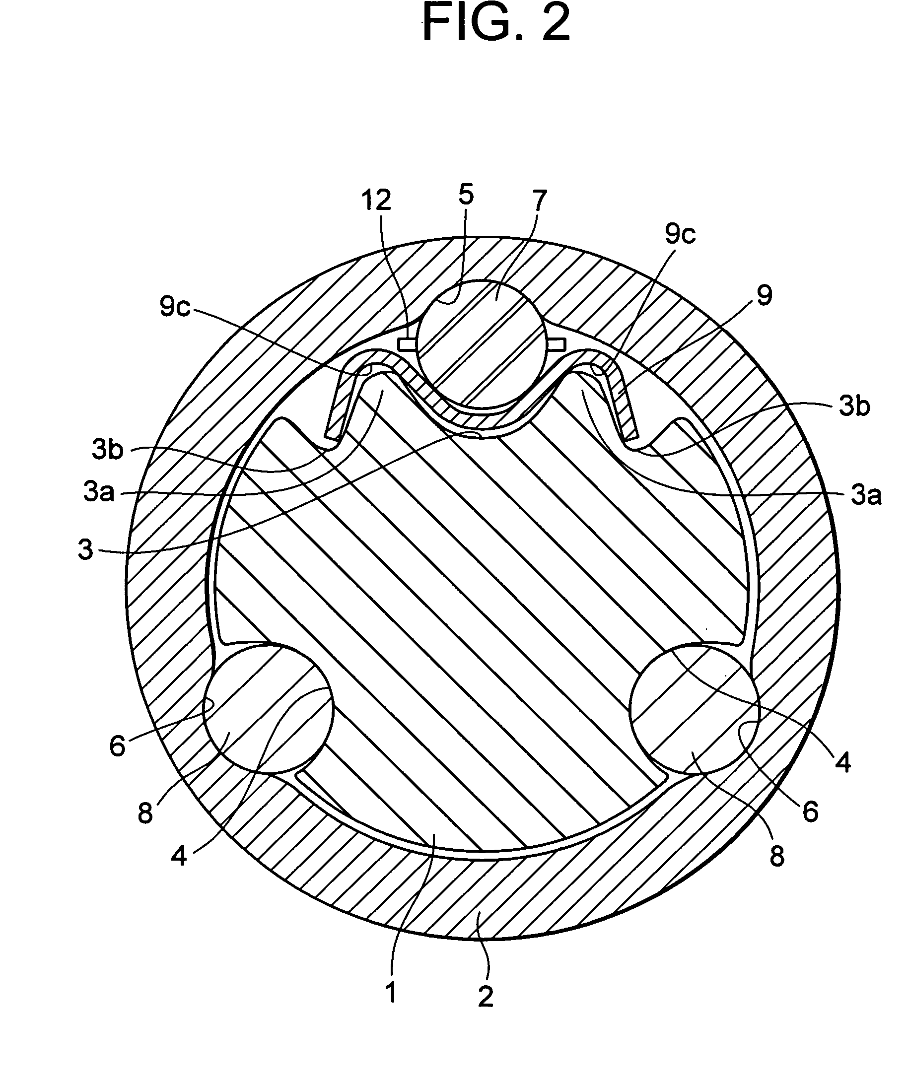
[0035]FIG. 1A is a side view of a telescopic shaft for vehicle steering according to a first embodiment of the present invention, and FIG. 1B is a perspective view thereof. FIG. 2 is a cross sectional view, taken along the line A-A in FIG. 1A.

[0036] As shown in FIGS. 1A and 1B, the telescopic shaft for vehicle steering (hereinafter called the “telescopic shaft”) comprises a male shaft 1 and a female shaft 2 which are fitted to each other to be unrotatable and slidable.

[0037] As shown in FIG. 2, three grooves 3, 4, 4 each having a substantially arch shape are provided on the outer peripheral surface of the male shaft 1 at regular intervals of 120° in the circumferential direction to be extended in the axial direction. To be corresponding thereto, also on the inner peripheral surface of the female shaft 2, three grooves 5, 6, 6 each having a substantially arch shape are provided at regular intervals of 120° in the circumferential direction to be extended in th...

second embodiment

of the Telescopic Shaft

[0074]FIG. 5A is a longitudinal cross sectional view of a telescopic shaft for vehicle steering according to a second embodiment of the present invention, and FIG. 5B is an enlarged transverse cross sectional view, taken along the line b-b in FIG. 5A. FIG. 6 is an exploded perspective view of the telescopic shaft for vehicle steering according to the second embodiment.

[0075] In the first embodiment described above, one set of first torque transmitting member 7 is provided between one pair of axial grooves 3, 5, and two sets of second torque transmitting members 8 are provided between two pairs of axial grooves 4, 6 which are provided at regular intervals of 120° in the circumferential direction with respect to the above one pair of the axial grooves 3, 5.

[0076] On the other hand, in the second embodiment, as shown in FIGS. 5A and 5B, the spherical members 7 serving as first torque transmitting members are respectively provided between three pairs of grooves ...


PUM


Abstract

Spherical members 7 are provided between plural pairs of axial grooves 3, 5 which are respectively formed on the outer peripheral surface of a male shaft 1 and on the inner peripheral surface of a female shaft 2, a leaf spring 9 for preload is interposed between the axial groove of the male shaft and the spherical member, and columnar members 8 are provided between another plural pairs of axial grooves 4, 6 which are respectively formed on the outer peripheral surface of the male shaft 1 and on the inner peripheral surface of the female shaft 2. Moreover, the radius of curvature of a transverse cross section of the axial groove 5 on the side of the female shaft 2 in which the spherical member 7 is rotated is set as 55% or less of the diameter of the spherical member 7.

Description

TECHNICAL FIELD [0001] The present invention relates to a telescopic shaft for vehicle steering which is installed in a steering shaft of a vehicle and in which a male shaft and a female shaft are fitted to each other to be mutually unrotatable and slidable. BACKGROUND ART [0002] A telescopic shaft of a steering mechanism of a vehicle is required to have a property of absorbing an axial displacement which is generated when the vehicle is running and of preventing such displacement or vibration from being propagated onto a steering wheel. Further, the telescopic shaft is also required to have a function of moving the position of the steering wheel in the axial direction and of adjusting this position in order to obtain an optimal position for the driver to drive the vehicle. [0003] In any event, the telescopic shaft is required to reduce rattling noise, to decrease backlash feeling on the steering wheel, and to reduce a sliding resistance during a sliding operation in the axial direc...

Claims


Application Information

Patent Timeline
IPC IPC(8): B62D1/19B62D1/20B62D1/16B62D1/18B62D1/185F16C3/035F16D3/06
CPCB62D1/16B62D1/185F16C3/035F16D3/065F16C29/007F16C29/04F16C29/123F16C2326/24
Inventor TANIGUCHI, MASATOYAMADA, YASUHISA
Owner NSK LTD
Why Eureka
Try Eureka