
Transparent conductor, method for producing same, and touch panel

Active Publication Date: 2018-04-26
TDK CORPARATION
View PDF0 Cites 5 Cited by
  • Summary
  • Abstract
  • Description
  • Claims
  • Application Information

AI Technical Summary

Benefits of technology

The present invention provides a transparent conductor that can prevent shading caused by differences in light transmission between conductive and insulating parts. The invention also provides a method for producing the conductor at high efficiency. Additionally, the invention can reduce shading in touch panels by using the transparent conductor.

Problems solved by technology

However, thickening of the ITO film leads to lowering of the transmittance.
In addition, it is typically difficult to perform thermal annealing for a substrate for a film at high temperature.
Thus, it is currently difficult to lower the resistance of an ITO film provided on a substrate for a film while the transmittance is kept high.

Method used


Image

  • Transparent conductor, method for producing same, and touch panel
  • Transparent conductor, method for producing same, and touch panel
  • Transparent conductor, method for producing same, and touch panel

Examples


example 1

(Production of Transparent Conductor)

[0154]A polyethylene terephthalate film with a thickness of 50 μm (manufactured by TORAY INDUSTRIES, INC., product number: UH13, refractive index: 1.61) was prepared. The PET film was used as the transparent resin substrate. A coating material for producing the hardcoat layer on the back surface of the PET film was prepared by using the following procedure.

[0155]The following raw materials were prepared.[0156]colloidal silica modified with reactive groups (dispersion medium: propylene glycol monomethyl ether acetate, nonvolatile content: 40% by mass): 100 parts by mass[0157]dipentaerythritol hexaacrylate: 48 parts by mass[0158]1,6-hexanediol diacrylate: 12 parts by mass[0159]photopolymerization initiator (1-hydroxycyclohexyl phenyl ketone): 2.5 parts by mass

[0160]The above raw materials were diluted with a solvent (propylene glycol monomethyl ether (PGMA)) and mixed together to disperse the components in the solvent. Thereby, a coating material w...

example 2

[0171]Transparent conductors (without the glass layer, with the glass layer) were produced in the same manner as in Example 1, except that the thickness of each of the transmittance-controlling layer and the metal oxide layer was changed as shown in Table 1, a ZnO—In2O3—TiO2—SnO2 target was used in formation of the metal oxide layer, and the high refractive index layer was formed between the transparent resin substrate and the transmittance-controlling layer. The composition of the target used for formation of the metal oxide layer was ZnO:In2O3:TiO2:SnO2=44:26:11:19 (mol %). The composition of the metal oxide layer formed was the same as the composition of the corresponding target. The composition, thickness, and refractive index of each layer are shown in Table 1.

[0172]The high refractive index layer was formed by using the following procedure. A resin composition containing zirconium oxide (ZrO2) (trade name: TYZ70, manufactured by TOYO INK CO., LTD., refractive index: 1.70) was ...

example 3

[0173]Transparent conductors (without the glass layer, with the glass layer) were produced in the same manner as in Example 2, except that the thickness of each of the transmittance-controlling layer and the high refractive index layer was changed as shown in Table 2, and the low refractive index layer was formed between the transparent resin substrate and the high refractive index layer. The composition, thickness, and refractive index of each layer are shown in Table 2.

[0174]The low refractive index layer was formed by using the following procedure. A resin composition containing silicon oxide (SiO2) (trade name: ENS653, manufactured by DIC Corporation, refractive index: 1.45) was diluted with propylene glycol monomethyl ether (PGMA) as a solvent to prepare a coating material with a nonvolatile content (NV) of 3% by mass. The coating material prepared was applied onto the other surface (front surface) of the transparent resin substrate to form the low refractive index layer. There...


PUM

PropertyMeasurementUnit
Fractionaaaaaaaaaa
Fractionaaaaaaaaaa
Fractionaaaaaaaaaa

Abstract

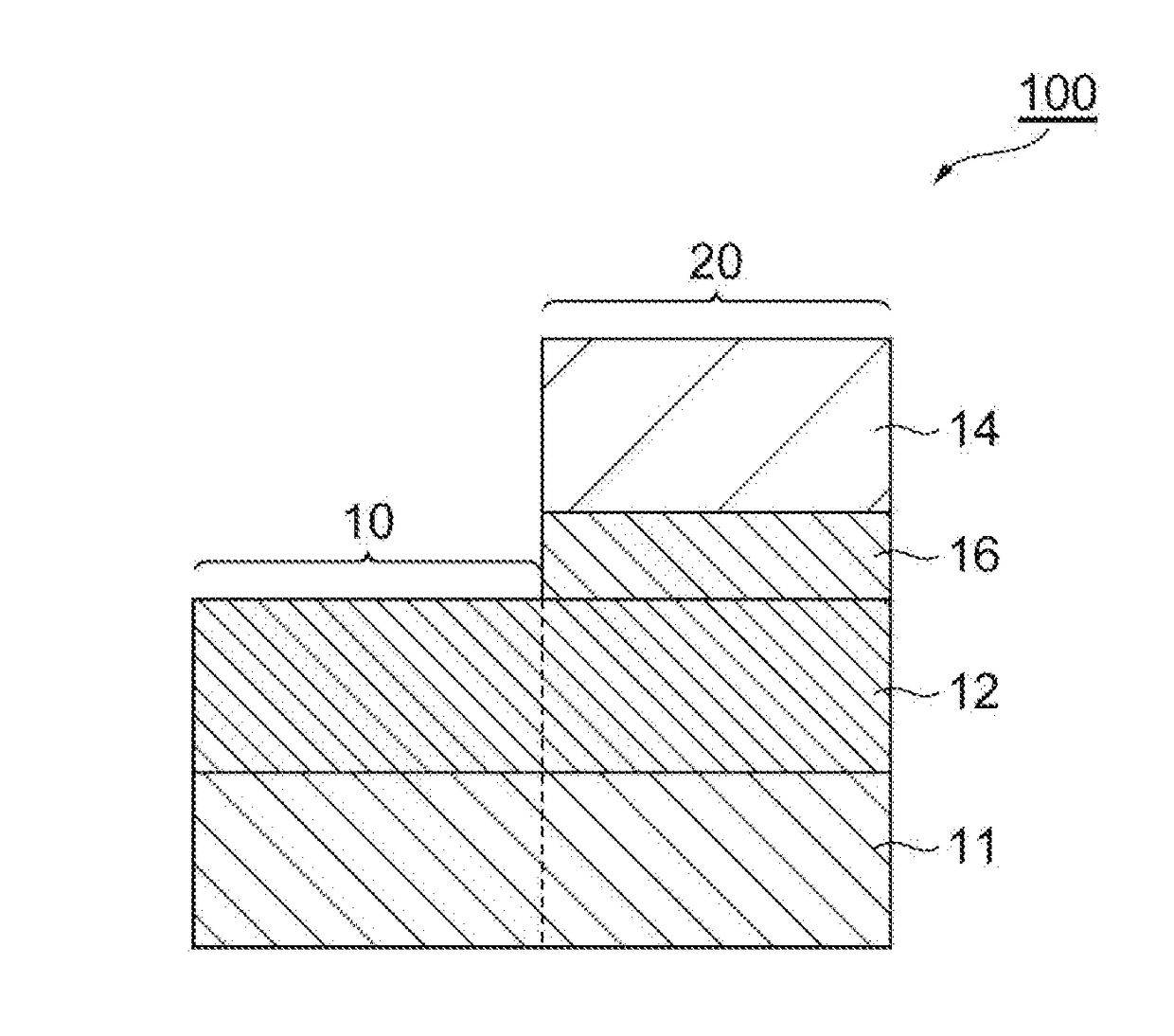
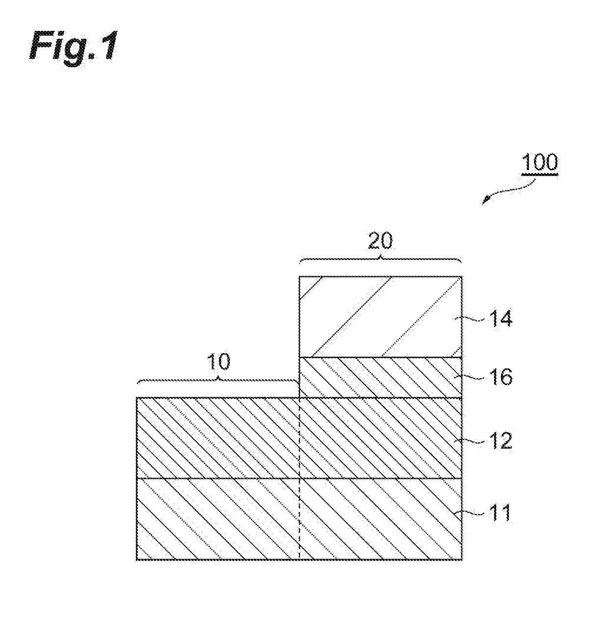
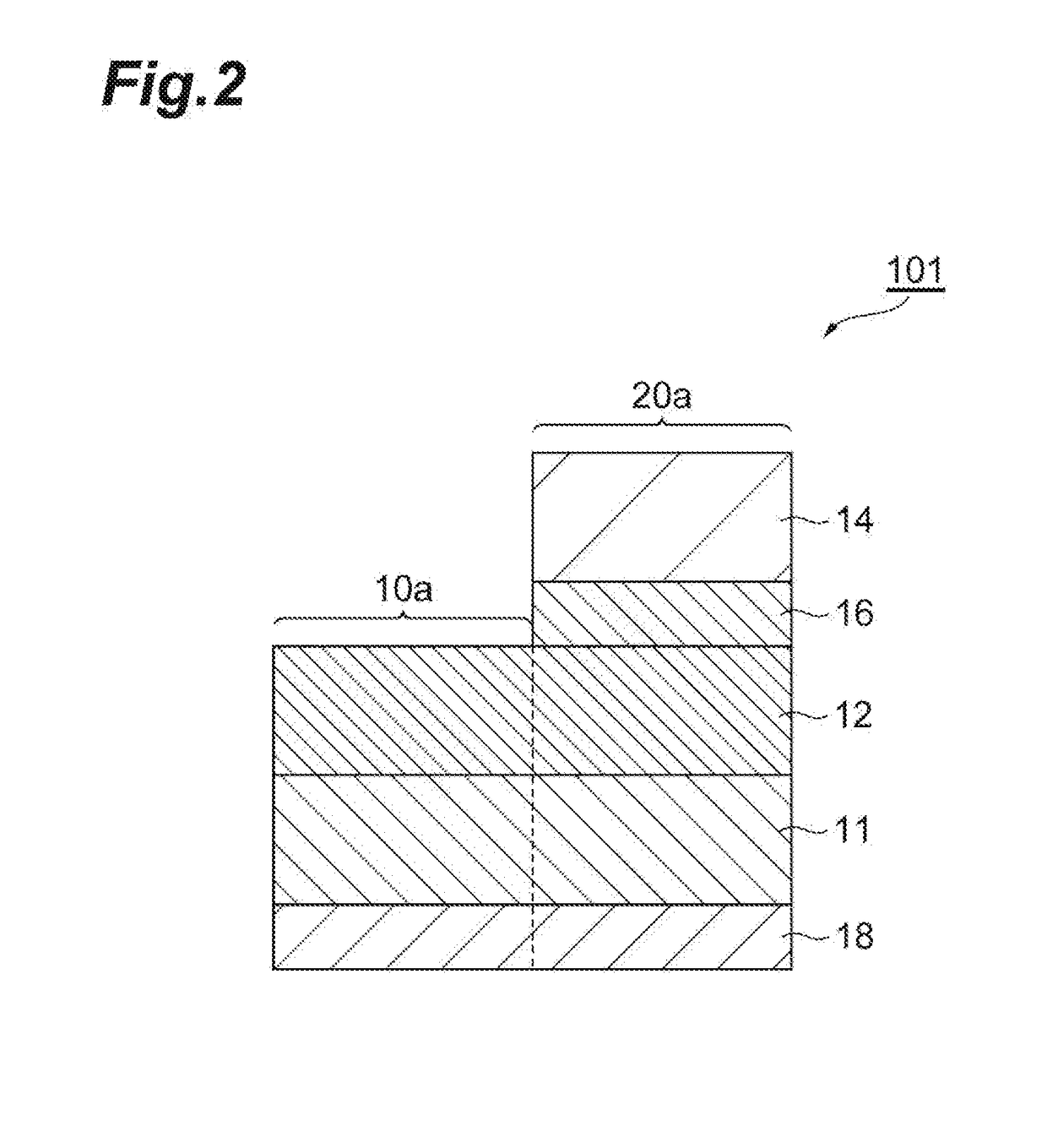
The transparent conductor involves a first laminate part including a transparent resin substrate and a transmittance-controlling layer, and a second laminate part including the transparent resin substrate, the transmittance-controlling layer, a metal layer containing silver or a silver alloy, and a metal oxide layer in the order presented. The first laminate part and the second laminate part are adjacent to each other in a direction perpendicular to the direction of lamination of the first laminate part and the second laminate part, and the difference between the transmittance of the first laminate part in the direction of lamination, T1, and the transmittance of the second laminate part in the direction of lamination, T2, (T2−T1) is 4% or more.

Description

TECHNICAL FIELD[0001]The present disclosure relates to a transparent conductor and a method for producing the same, and a touch panel using the transparent conductor.BACKGROUND ART[0002]Transparent conductors are used for displays such as liquid crystal displays (LCDs), plasma display panels (PDPs), and electroluminescence panels (organic EL, inorganic EL), and transparent electrodes for solar cells or the like. In addition, transparent conductors are used for electromagnetic insulation films and infrared shield film. For a material of a metal oxide layer of a transparent conductor, ITO, which is a substance obtained by adding tin (Sn) to indium oxide (In2O3), is widely used.[0003]Terminals provided with a touch panel such as smartphones and tablet terminals have been rapidly spreading in recent years. They have a configuration in which a touch sensor part is provided on a liquid crystal panel, and a cover glass is provided on the outermost surface. The touch sensor part is configur...

Claims


Application Information

Patent Timeline
IPC IPC(8): G06F3/044B32B15/08C23F1/00
CPCG06F3/044B32B15/08C23F1/00B32B2307/412B32B2307/202B32B2307/418B32B2457/208G06F2203/04103H01B5/14H01B13/0036B32B9/00G06F3/041H01B13/00H05K1/0274H05K1/0289H05K1/0313H05K1/09H05K2201/0108H05K2201/0338G06F3/0446G06F3/0445
Inventor SHINGAI, HIROSHITAMAGAWA, YOSHIHISASAKURAI, MOTOHIRO
Owner TDK CORPARATION
Learn More