
Three-dimensional formation apparatus, three-dimensional formation method, and computer program

Active Publication Date: 2015-10-01
SEIKO EPSON CORP
View PDF2 Cites 5 Cited by
  • Summary
  • Abstract
  • Description
  • Claims
  • Application Information

AI Technical Summary

Benefits of technology

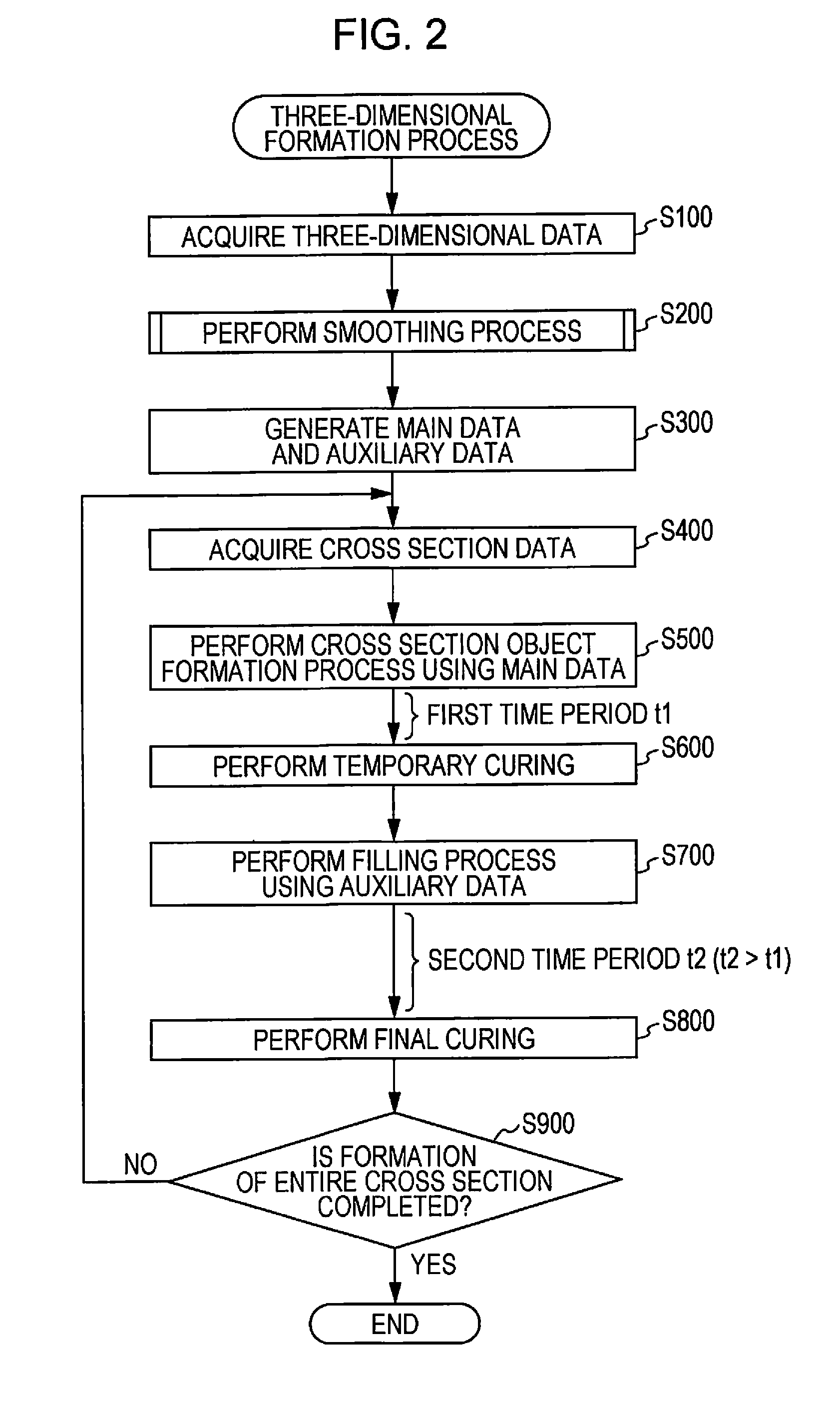
The invention provides a three-dimensional formation apparatus that can form a three-dimensional object using a liquid material. The apparatus includes a head unit that discharges liquid in a certain direction, and a control unit that forms objects by repeatedly discharging liquid in a cross section object formation process. The control unit controls the head unit to form a hollow inside the object where the outline is simultaneously changed in two directions. Afterward, the apparatus fills the hollow with liquid to prevent jaggy (distortion of shape) and to accurately discharge the liquid. The shape of the object can be represented with polygons, and the first element can be accurately specified based on its gradation value. The second element can be an element adjacent to a direction of a large component among components in the second and third directions.

Problems solved by technology

However, when small dots are formed in a portion where the deviation of coordinates is generated in a case of forming a three-dimensional object, a height of the portion is decreased, and it is difficult to form an appropriate three-dimensional shape.
Accordingly, it is difficult to simply apply the printing technology of a two-dimensional image to the formation process of a three-dimensional object.

Method used


Image

  • Three-dimensional formation apparatus, three-dimensional formation method, and computer program
  • Three-dimensional formation apparatus, three-dimensional formation method, and computer program
  • Three-dimensional formation apparatus, three-dimensional formation method, and computer program

Examples


first embodiment

A. First Embodiment

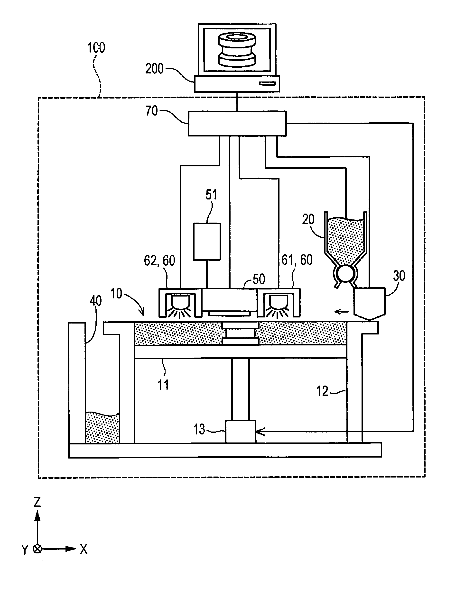
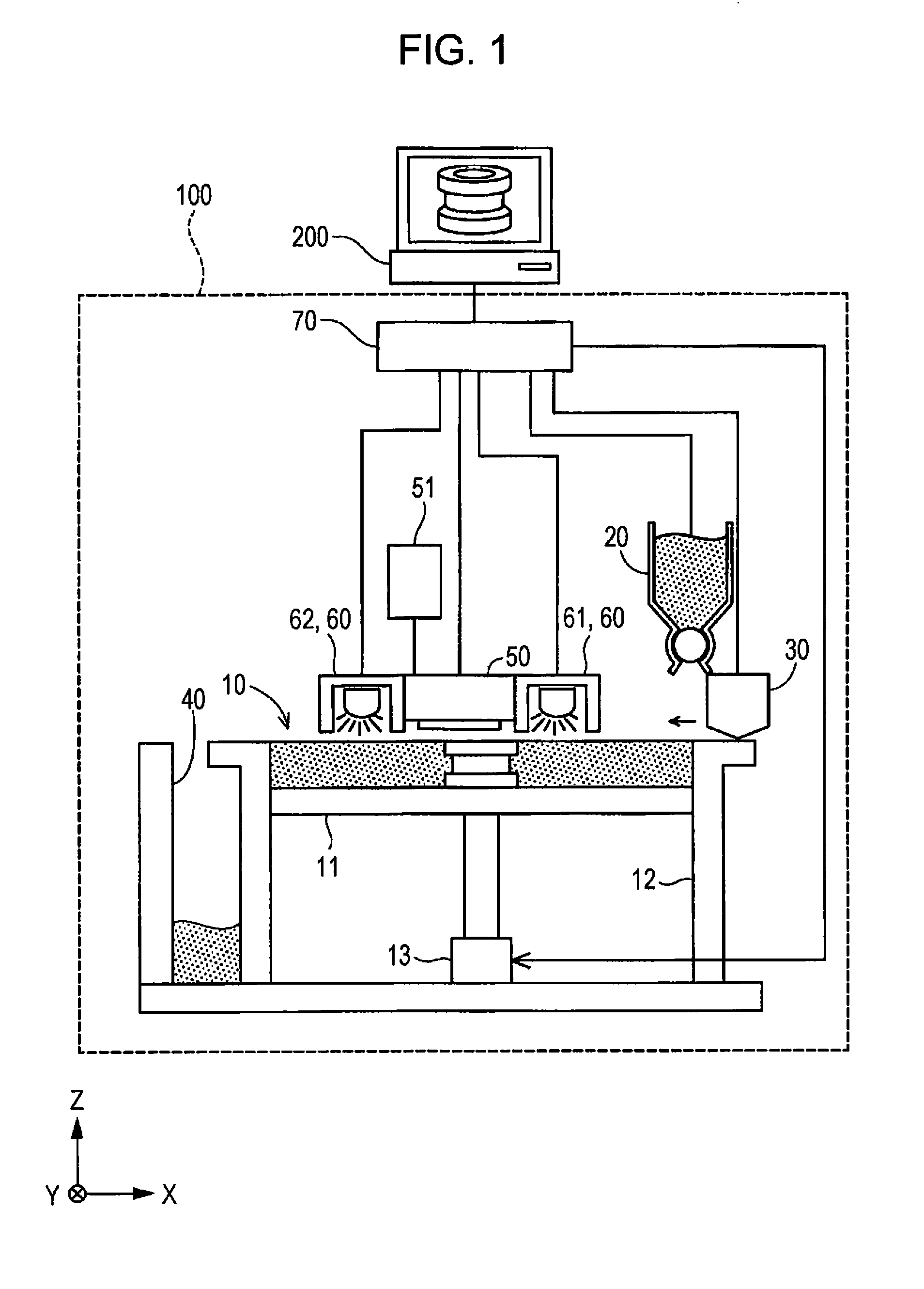
[0029]FIG. 1 is an explanatory diagram showing a schematic configuration of a three-dimensional formation apparatus as a first embodiment. A three-dimensional formation apparatus 100 includes a formation unit 10, a powder supply unit 20, a flattening mechanism 30, a powder collection unit 40, a head unit 50, curing energy application units 60, and a control unit 70. A computer 200 is connected to the control unit 70. The three-dimensional formation apparatus 100 and the computer 200 can be collectively treated as a three-dimensional formation apparatus in a broad sense. FIG. 1 shows an X direction, a Y direction, and a Z direction orthogonal to each other. The Z direction is a direction along a vertical direction and the X direction is a direction along a horizontal direction. The Y direction is a direction vertical to the Z direction and the X direction. The Z direction corresponds to a first direction, the X direction corresponds to a second direction, and the Y...

second embodiment

B. Second Embodiment

[0072]The three-dimensional formation apparatus 100 of the first embodiment forms the three-dimensional object using the curable liquid and the powder. According to this, the three-dimensional formation apparatus 100 of a second embodiment forms the three-dimensional object using a support material, in addition to the curable liquid. The support material of the embodiment is liquid which is cured by curing energy equivalent to the curing energy for curing the curable liquid, and is a material which can be dissolved by putting into water or a predetermined solution after the curing and can be easily removed. When the support material is discharged to the outside of the outline of the three-dimensional object, it is possible to prevent the spread of the outline of the three-dimensional object formed with the curable liquid to the outside. In the three-dimensional formation apparatus 100 of the second embodiment, nozzles for discharging the curable liquid and the su...

third embodiment

C. Third Embodiment

[0074]FIG. 10 is a flowchart showing a smoothing process of a third embodiment. In the first embodiment, the three-dimensional data representing the shape of the three-dimensional object is represented as the three-dimensional polygon data. Meanwhile, in the third embodiment, the three-dimensional data is represented as the raster data for each cross section. The configurations of the three-dimensional formation apparatus 100 and the computer 200 of the third embodiment are the same as those in the first embodiment.

[0075]In the smoothing process of the embodiment, first, the computer 200 reads the three-dimensional data (Step S230). As described above, in the embodiment, the three-dimensional data is configured with the raster data for each cross section.

[0076]Then, the computer 200 compares a resolution in the XY direction of the read three-dimensional data (XY input resolution) and formation resolution in the XY direction of the three-dimensional formation appar...


PUM

PropertyMeasurementUnit
Fractionaaaaaaaaaa
Timeaaaaaaaaaa
Volumeaaaaaaaaaa

Abstract

A three-dimensional formation apparatus includes a head-unit which can discharge liquid in a first-direction and a control-unit which controls the head-unit. The control-unit forms a hollow on a changed portion where an outline of a cross section object is simultaneously changed in a second-direction and a third-direction towards the inside from the outline of the cross section object in the second-direction or the third-direction, in a first cross section object formation process and executes a filling process of discharging the liquid containing a second quantity which is larger than a first quantity to the hollow so as to come in contact with the cross section object formed in the first cross section object formation process, to fill at least a part of the hollow with the liquid, after the first cross section object formation process is executed and before the second cross section object formation process is executed.

Description

BACKGROUND[0001]1. Technical Field[0002]The present invention relates to a three-dimensional formation apparatus.[0003]2. Related Art[0004]In recent years, a three-dimensional formation apparatus using a printing technology has been paid attention. For example, an ink jet technology generally used in a printing technology is used in three-dimensional formation apparatuses disclosed in JP-A-06-218712, JP-A-2005-67138, and JP-A-2010-58519. In the three-dimensional formation apparatuses using an ink jet technology, a three-dimensional object is formed by performing a step of discharging liquid having curing properties and forming a cross section object for a layer along a horizontal direction (XY direction), over a plurality of layers in a height direction (Z direction).[0005]In a predetermined formation resolution, the ink jet-type three-dimensional formation apparatus discharges liquid to predetermined coordinates and forms dots to form a cross section object. Accordingly, an outline...

Claims


Application Information

Patent Timeline
IPC IPC(8): B29C67/00
CPCB29C67/0051B33Y10/00B29L2009/00B33Y50/00B33Y30/00B29C64/135B29C64/112B29C64/165B29C64/393B33Y50/02
Inventor OKAMOTO, EIJI
Owner SEIKO EPSON CORP
Learn More