Method for forming re coating film or re-cr alloy coating film through electroplating

Inactive Publication Date: 2005-06-16
TOSHIO NARITA +1
View PDF4 Cites 5 Cited by
  • Summary
  • Abstract
  • Description
  • Claims
  • Application Information

AI Technical Summary

Benefits of technology

[0033] In the methods set forth in the first to fourth aspects of the present invention, the plating bath may contain an ammonium ion in a concentration of 0.0001 to 5.0 mol/L, and/or a boric acid in a concentration of 0.0001 to 5.0 mol/L. The addition of these substances provides stability in the plating bath to allow the film to be formed with a homogeneous thickness. The use of a concentration of ammonium ion or boric acid less than 0.0001 mol/L causes spots in a plated film, and the use of a concentration of ammonium ion or boric acid grater than 5.0 mol/L causes creation of an insoluble substance to result in deteriorated flowability of the aqueous solution. Therefore, the concentration of the ammonium ion and/or boric acid is preferably set in the range of 0.0001 to 5.0 mol/L.
[0034] In the methods set forth in the first to fourth aspects of the present invention, the plating bath may contain a bromine ion in a concentration of 0.0001 to 5.0 mol/L. This prevent the generation of harmful chlorine gas. This effect cannot be obtained by a concentration of bromine ion less than 0.0001 mol/L, and the use of a concentration of bromine ion greater tha

Problems solved by technology

On the other hand, it involves problems, such as, (i) many restrictions on the size and shape of a substrate, (ii) the need for a large-scaled apparatus and complicated operations and (iii) a relatively large number of defects or cracks in an obtained f

Method used


Image

  • Method for forming re coating film or re-cr alloy coating film through electroplating
  • Method for forming re coating film or re-cr alloy coating film through electroplating
  • Method for forming re coating film or re-cr alloy coating film through electroplating

Examples


Example

INVENTIVE EXAMPLE 1

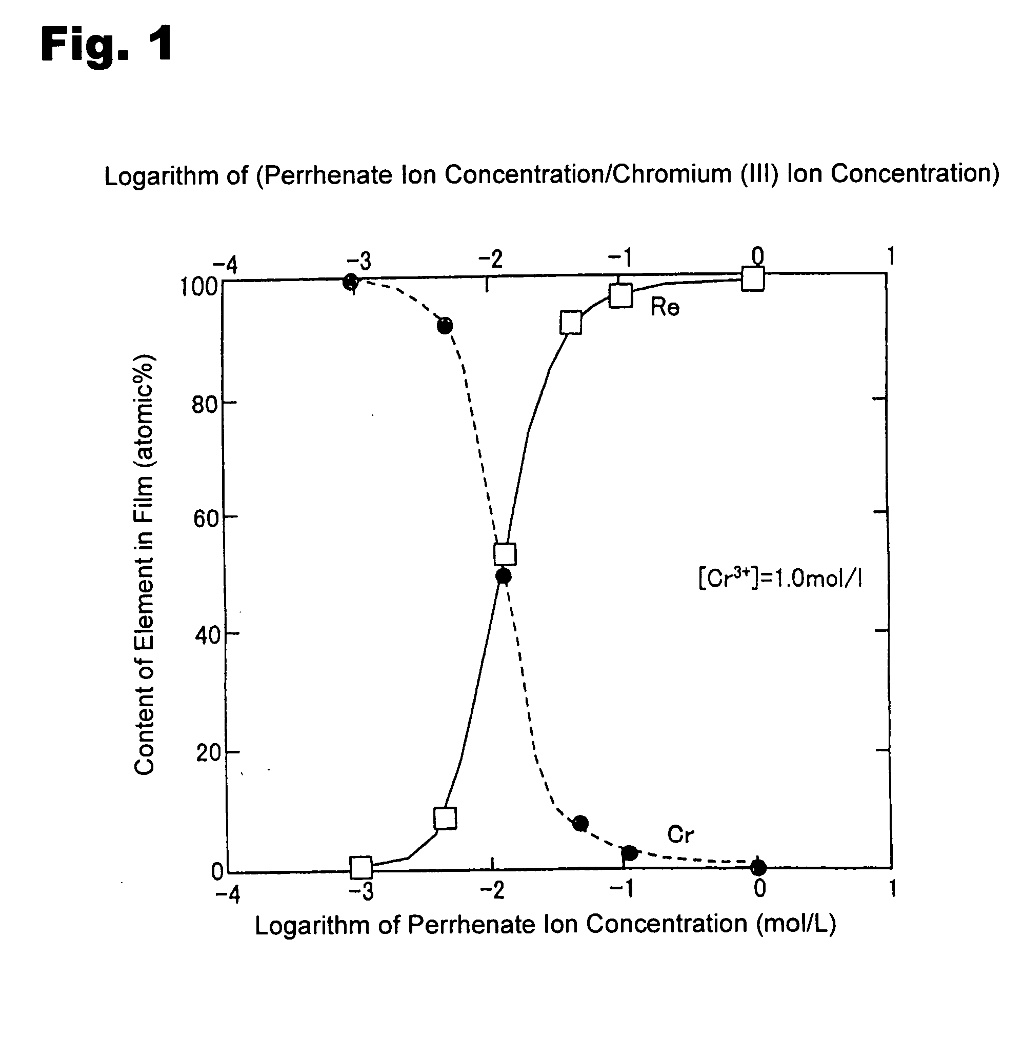
[0040] A copper plate was subjected to degreasing / cleaning, and used as a substrate. A solution was prepared using chromium chloride to have a Cr3+ ion in a concentration of 1.0 mol / L and a ReO4− ion in a concentration of 0.005 mol / L. In addition to the ReO4− ion and Cr3+ ion, 1.5 mol / L of acetic acid, 0.5 mol / L of ammonium chloride and 0.5 mol / L of potassium bromide were added to the solution to prepare a plating bath. The pH of the plating bath was adjusted at 4 using sulfuric acid and sodium hydrate. Then, an electroplating process was performed under a plating bath temperature of 35° C. and a current density of 100 mA / cm2.

Example

INVENTIVE EXAMPLE 2

[0041] Except that the concentration of the ReO4− was set at 0.01 mol / L, an electroplating process was performed under the same conditions as those in Inventive Example 1.

Example

INVENTIVE EXAMPLE 3

[0042] Except that the concentration of the ReO4− was set at 0.05 mol / L, an electroplating process was performed under the same conditions as those in Inventive Example 1.


PUM

PropertyMeasurementUnit
Temperatureaaaaaaaaaa
Fractionaaaaaaaaaa
Fractionaaaaaaaaaa

Abstract

Disclosed is a method for forming: a Re—Cr alloy film consisting of Re in the range of greater than 0 (zero) to less than 98% by atomic composition, and the remainder being Cr except inevitable impurities; a Re-based film consisting of 98% or more, by atomic composition, of Re, with the remainder being Cr and inevitable impurities; or a Re—Cr—Ni alloy film consisting of Re in the range of 50 to less than 98% by atomic composition, Cr in the range of 2 to less than 45% by atomic composition, and the remainder being Ni except inevitable impurities. The method comprises performing an electroplating process using an electroplating bath containing an aqueous solution which includes a perrhenate ion and a chromium (III) ion. The present invention allows a Re—Cr alloy, Re-based or Re—Cr—Ni alloy film usable as a corrosion-resistant alloy coating for a high-temperature component or the like to be formed through an electroplating process using an aqueous solution, so as to provide heat/corrosion resistances to the component, even if it has a complicated shape, in a simplified manner at a low cost.

Description

TECHNICAL FIELD [0001] The present invention relates to a method for forming a Re—Cr alloy or Re-based film usable as a corrosion-resistant coating for high-temperature components or the like. BACKGROUND ART [0002] A Ni-based superalloy substrate for use in a blade for jet engines, gas turbines or the like is strictly required to have high oxidation resistance and corrosion resistance. Such required high-temperature oxidation resistance has been obtained through a surface diffusion treatment, for example, by coating a substrate surface with an Al2O3 film. For covering the insufficient performance of this treatment, there has also been developed a technique for forming a diffusion barrier layer of Pt or the like on a substrate. Rhenium (Re) can be used as the diffusion barrier layer to provide enhanced high-temperature corrosion resistance. Re excellent in thermal shock resistance is also used as high-temperature members or components of various combustors, such as a rocket-engine co...

Claims


Application Information

Patent Timeline
IPC IPC(8): C25D3/56
CPCC25D3/56
Inventor NARITA, TOSHIOHAYASHI, SHIGENARIYOSHIOKA, TAKAYUKIYAKUWA, HIROSHISOUMA, MICHIAKI
Owner TOSHIO NARITA
Why Eureka
Try Eureka