Resin casing

a technology of resin casing and resin cover, which is applied in the direction of caps, electric apparatus casings/cabinets/drawers, liquid handling, etc., can solve the problems of warping of the opposite end of the resin cover (the short side of the rectangle), deformation such as warps and depressions, and the flowability of the resin deteriorates, so as to increase the strength of the top plate and the stiffness of the resin casing. , the effect of increasing th

Active Publication Date: 2014-10-02
HITACHI ASTEMO LTD
View PDF8 Cites 0 Cited by
  • Summary
  • Abstract
  • Description
  • Claims
  • Application Information

AI Technical Summary

Benefits of technology

[0008]Moreover, because the grid-like ribs are provided on the rear surface of the resin cover, a ribbed portion and a crossover portion of the ribs become thick, and hence, there are large variations in the thickness of the cover. When there are large variations in the thickness, flowability of the resin deteriorates at the time of molding by a mold, and deformations such as warps and depressions are likely to occur at the time of curing the resin. Particularly, when the resin cover is molded by using resin added with glass fiber for increasing the strength of the resin cover, deformations such as warps and depressions are likely to occur more easily, because the flowability of the glass fiber becomes impaired due to the variations in the thickness.
[0009]In view of the above situation, it is an object of the present invention to provide a resin casing that prevents deformations such as warps by increasing resin moldability, while ensuring stiffness of the resin casing.
[0013]According to the resin casing of the aspect according to the present invention, a plurality of depressions is formed respectively on the outer surface and the inner surface of any of or both of the top plate of the resin cover and the bottom plate of the resin case, and the depressions are alternately arranged with respect to the outer surface and the inner surface, on the outer surface and the inner surface along a predetermined direction as seen in a plan view. As a result, the depressions are formed and arranged in a state of being dispersed substantially evenly on the outer surface and the inner surface. Accordingly, the strength becomes substantially the same between the outer surface and the inner surface, while increasing the strength of the top plate of the resin cover or the bottom plate of the resin case. Hence, the occurrence of warps due to a strength difference between the outer surface side and the inner surface side can be prevented when the resin is cured at the time of molding, while ensuring the stiffness of the resin casing.
[0014]Moreover, because the depression are alternately arranged on the outer surface and the inner surface, the depressions are formed and arranged in the state of being dispersed substantially evenly on the outer surface and the inner surface. Hence, variations in the thickness of the top plate of the resin cover or the bottom plate of the resin case can be reduced. As a result, the flowability of the resin can be improved at the time of molding by a mold, and the occurrence of deformations such as warps and depressions at the time of curing the resin can be prevented.

Problems solved by technology

Therefore, when the resin is cured at the time of molding, the opposite ends of the resin cover (the short sides of a rectangle) are likely to warp outward.
When there are large variations in the thickness, flowability of the resin deteriorates at the time of molding by a mold, and deformations such as warps and depressions are likely to occur at the time of curing the resin.
Particularly, when the resin cover is molded by using resin added with glass fiber for increasing the strength of the resin cover, deformations such as warps and depressions are likely to occur more easily, because the flowability of the glass fiber becomes impaired due to the variations in the thickness.

Method used


Image

  • Resin casing
  • Resin casing
  • Resin casing

Examples


first embodiment

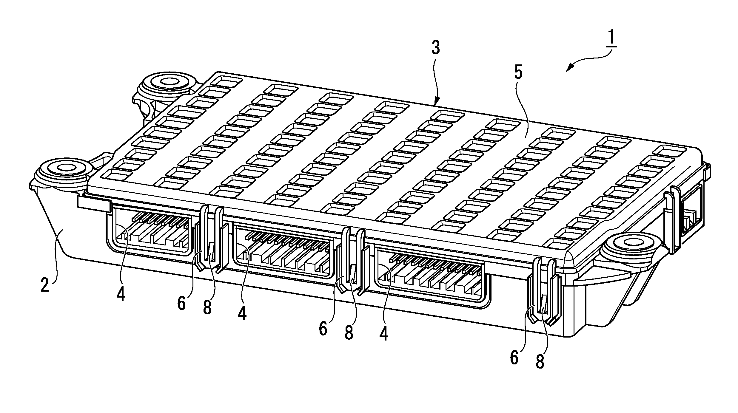
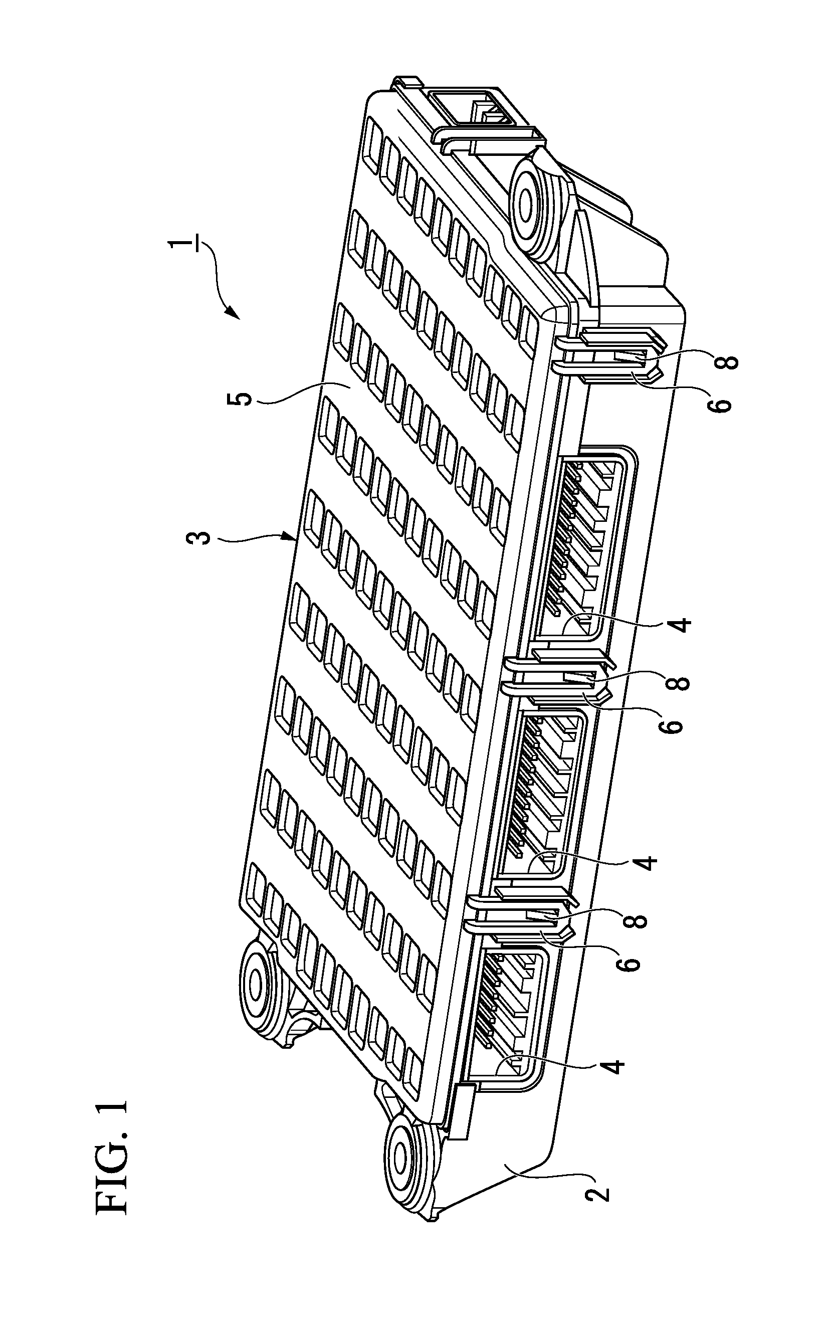
[0022]FIG. 1 is a perspective view showing a schematic configuration of the resin casing according to the present invention. Reference symbol 1 in FIG. 1 denotes a resin casing for an ECU (Electronic Control Unit) for a vehicle, that is, a resin casing for housing the electronic control unit.

[0023]The resin casing 1 includes a case made of resin (resin case) 2 that houses and holds a circuit board (not shown), and a cover made of resin (resin cover) 3 attached to the case 2.

[0024]The case 2 has a box shape having a substantially rectangular (substantially oblong) bottom plate (not shown) as seen in a plan view. A resin composition in which glass fiber is added to a resin such as PBT (polybutylene terephthalate) as a reinforcing material, is used for the case 2, and the case 2 is molded by a mold. The case 2 has a recess (not shown) for housing and holding a circuit board inside of the central part thereof, and the circuit board is held in the recess. Moreover, a plurality of connect...

second embodiment

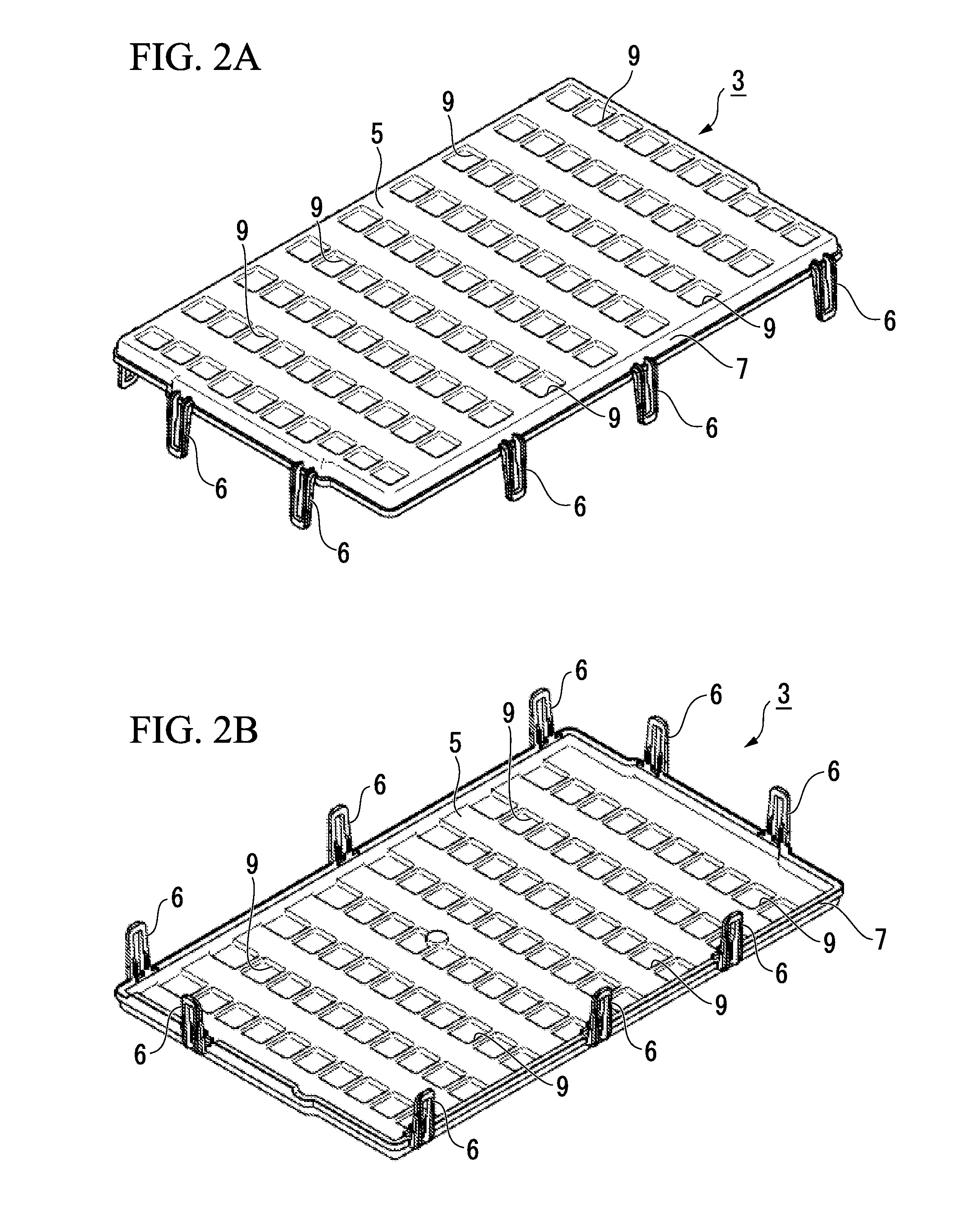
[0039]FIG. 4A is a perspective view of a top plate of a resin cover of a resin casing according to the present invention. Reference symbol 5A in FIG. 4A denotes a top plate of a cover (resin cover). The top plate 5A is formed in a square shape. Although not shown, fitting pieces 6 as shown in FIGS. 2A and 2B are formed on the cover having the top plate 5A. Moreover, a case (resin case) attached with the cover has a bottom plate formed in a square shape corresponding to the cover.

[0040]In the top plate 5A, a plurality of depressions 9a is formed in a square shape, and these depressions 9a are arranged with respect to a surface (outer surface) and a rear surface (inner surface) alternately on the surface and on the rear surface along a predetermined direction as seen in a plan view.

[0041]That is to say, the depressions 9a are arranged in a staggered arrangement respectively on the surface and the rear surface. Accordingly, in any direction of a longitudinal direction and a horizontal ...

third embodiment

[0044]FIG. 4B is a perspective view of a top plate of a resin cover of a resin casing according to the present invention. In FIG. 4B, reference symbol 5B denotes a top plate of a cover (resin cover). The top plate 5B is also formed in a square shape. Although not shown, fitting pieces 6 as shown in FIGS. 2A and 2B are also formed on the cover having the top plate 5B. Moreover, a case (resin case) attached with the cover has a bottom plate formed in a square shape corresponding to the cover.

[0045]In the top plate 5B, a plurality of depressions 9a is formed in a square shape, and these depressions 9a are arranged with respect to a surface (outer surface) and a rear surface (inner surface) alternately on the surface and on the rear surface along a predetermined direction as seen in a plan view.

[0046]That is to say, the depressions 9a are formed in a wavelike formation respectively on the surface and on the rear surface, and are alternately arranged on the surface and on the rear surfac...


PUM


Abstract

A resin casing includes a resin case and a resin cover attached to the resin case. A plurality of depressions is formed respectively on an outer surface and an inner surface of a top plate of the resin cover. The depressions are alternately arranged on the outer surface and the inner surface along a predetermined direction as seen in a plan view.

Description

CROSS-REFERENCE TO RELATED APPLICATION[0001]Priority is claimed on Japanese Patent Application No. 2013-070449, filed Mar. 28, 2013, the content of which is incorporated herein by reference.BACKGROUND[0002]1. Field of the Invention[0003]The present invention relates to a resin casing.[0004]2. Description of the Related Art[0005]In various types of electronic equipment, electronic parts, an electronic circuit, and an electronic device constituting the electronic equipment are incorporated in a printed circuit board, and housed in a resin casing including a resin case and a resin cover. For example, when an electronic control unit as the electronic equipment is to be housed in a resin casing, if a board area of the electronic control unit increases, an area of a top plate of the resin cover also increases. Accordingly, the strength of the resin cover needs to be increased for the increased area of the resin cover.[0006]Under such a background there has conventionally been known a resi...

Claims


Application Information

Patent Timeline
Patent Type & Authority Applications(United States)
IPC IPC(8): B65D43/02
CPCB65D43/0212H05K5/0091H05K5/0047H01L21/67333
Inventor YAMANA, HIROKAZU
Owner HITACHI ASTEMO LTD
Why Eureka
Try Eureka