Method for manufacturing coated panels

a coating and panel technology, applied in the direction of natural patterns, thin material processing, textiles and papermaking, etc., can solve the problems of unnatural appearance of the respective structure, difficult to realize the structure with acute angles by these techniques, and many to be desired in respect of flexibility and/or in respect of feasible structures, etc., to reduce the uv sensitivity of the pattern, reduce wear or scratches, and reduce the effect of wear and tear

Active Publication Date: 2013-06-18
FLOORING IND LTD
View PDF20 Cites 62 Cited by
  • Summary
  • Abstract
  • Description
  • Claims
  • Application Information

AI Technical Summary

Benefits of technology

[0009]Due to the fact that at least two prints or print layers are provided on top of each other, a level variance may be created in the top layer, whereby more complex and / or more pronounced structures can be obtained. Preferably, protrusions are used which are formed with 3 or more, for example, up to 10 prints provided on top of each other, which considerably enhances the depth resolution, while still obtaining an economical process. Of course, not necessarily all protrusions of the respective structure must be constructed of an equally high number of prints or print layers provided on top of each other. By varying the number of prints provided on top of each other depending on the protrusion, a larger variation in the respective structure may be obtained.
[0011]According to a first embodiment, two or more prints or print layers provided on top of each other show an identical pattern in a cross-section of the respective protrusion. By this, it is meant that the respective protrusion, viewed in a local cross-section, consists of two or more prints or print layers covering each other substantially or even almost perfectly. This embodiment allows performing relatively large level variances, wherein the respective protrusion, at least in the respective cross-section, possibly may be provided with straight walls or relatively acute angles. Still better, the respective protrusion, for the major part thereof, has cross-sections in which said print layers cover each other substantially or even almost perfectly.
[0012]According to a second embodiment, two or more prints or print layers provided on top of each other show a different pattern in a cross-section of the respective protrusion, wherein the print located on top preferably has a smaller printed surface. This means that, in the case of a smaller printed surface, the respective protrusion, viewed in a local cross-section, consists of two or more prints or print layers, which do not cover each other entirely. This preferred embodiment allows realizing protrusions with an inclined wall, which as such increases the number of possibly achievable structures. Still better, the respective protrusion, for the major part thereof, has cross-sections in which the print layers show a different pattern, in other words, a different printed surface. It is clear that according to another possible embodiment of this second embodiment, the print or print layer lying on top may have a larger printed surface, as a result of which the underlying print layer possibly may be covered entirely.
[0016]The step in which the substrate is printed may be performed by means of one or more digitally controlled inkjet printing units. The use of inkjet printing units for printing on substrates of panels is known as such, for example, from the already mentioned WO 01 / 48333 and EP 1 872 959. The inventors have found that the use of digitally controlled printing units is advantageous with the method of the present invention, as they allow a precise and repeatable printing, such that the various print layers, if necessary, can be applied perfectly on top of each other or can be aligned in mutual respect. It is noted that, according to the state of the art, never overlapping print layers have been formed by inkjet printing units, the print layers forming a structure of protrusions, but that, if several of such printing units were applied, these finally resulted in a flat print. According to the present invention, the structure variation obtained by the overlapping prints is present in the print of the final coated panels. The obtained structure is noticeably present at the surface of the coated panel, although this is not necessarily so.
[0017]The method may comprise a step in which the substrate is provided with a transparent or translucent layer, which is provided on top of the prints. Although it is not excluded that, by means of the transparent or translucent layer, finally a flat surface is obtained, preferably at least a portion of the already formed protrusions, or even all of the protrusions, manifest themselves through the transparent or translucent layer, such that they preferably remain tangibly and visibly present at the final surface of the decorative top layer. When one or several protrusions are completely flattened out by means of the transparent or translucent layer, it is preferred that the built-up protrusions remain at least visibly present through the transparent or translucent layer. In this way, particular depth effects still can be achieved without a structure effect on the final surface. Such depth effects are less sensitive to wear, as they are embedded and are not present at the surface of the coated panel as projecting wear-sensitive portions.
[0018]It is noted that the above-mentioned transparent or translucent layer may comprise ingredients which protect the underlying print layers, such as hard particles which reduce possible wear or scratches, or ingredients which restrict the aging of the color of an underlying pattern, such as ingredients reducing the UV sensitivity of the pattern.

Problems solved by technology

Moreover, the above-mentioned techniques leave much to be desired in respect to flexibility and / or in respect to feasible structures.
Thus, for example, it is difficult to realize structures with acute angles by these techniques.
The relatively strongly rounded portions, which are difficult to avoid in the state of the art, lead to an unnatural appearance of the respective structure.
Also, obtaining deep structures is not simple with the known techniques.

Method used


Image

  • Method for manufacturing coated panels
  • Method for manufacturing coated panels
  • Method for manufacturing coated panels

Examples


Embodiment Construction

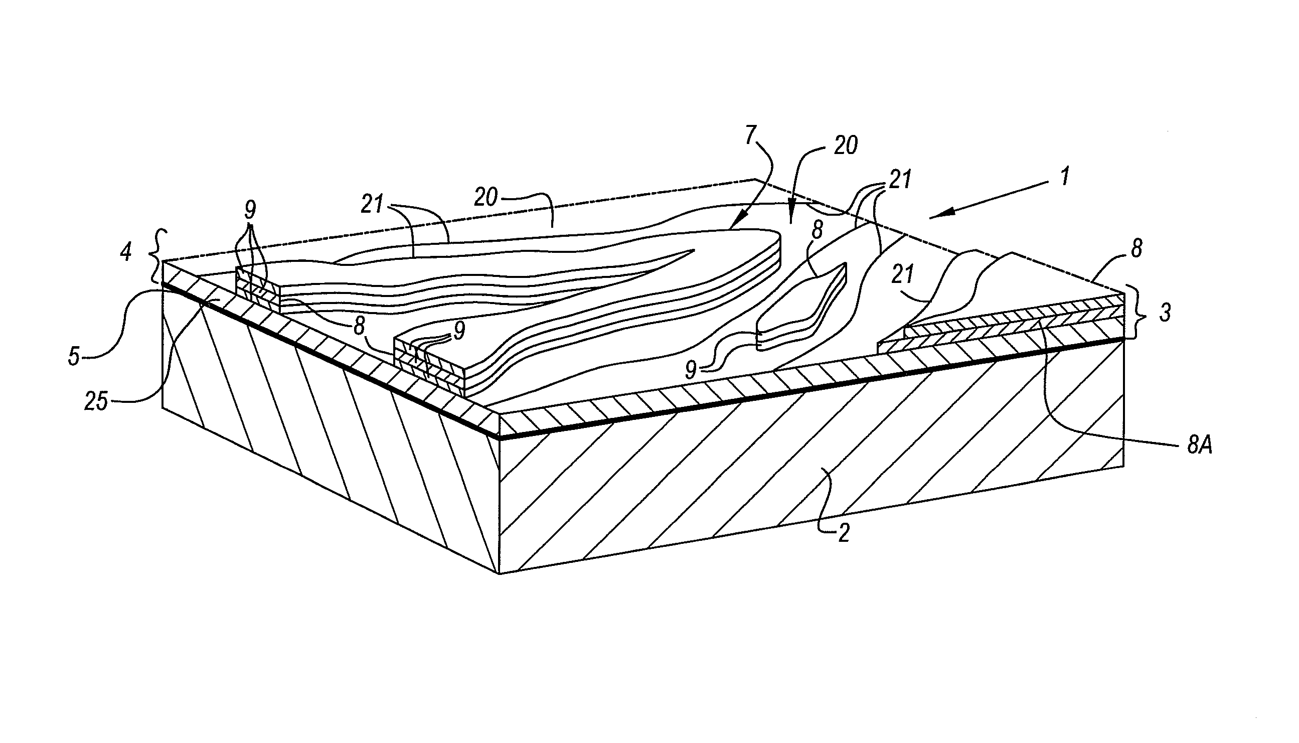
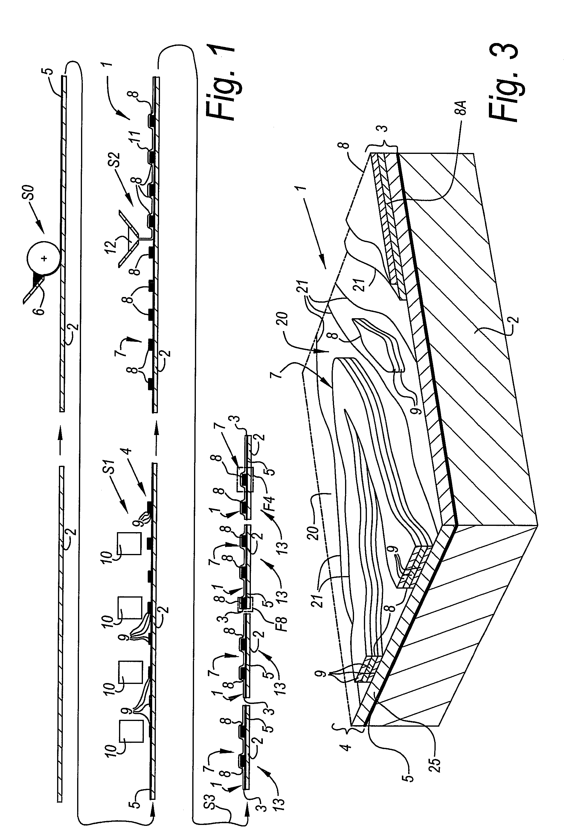
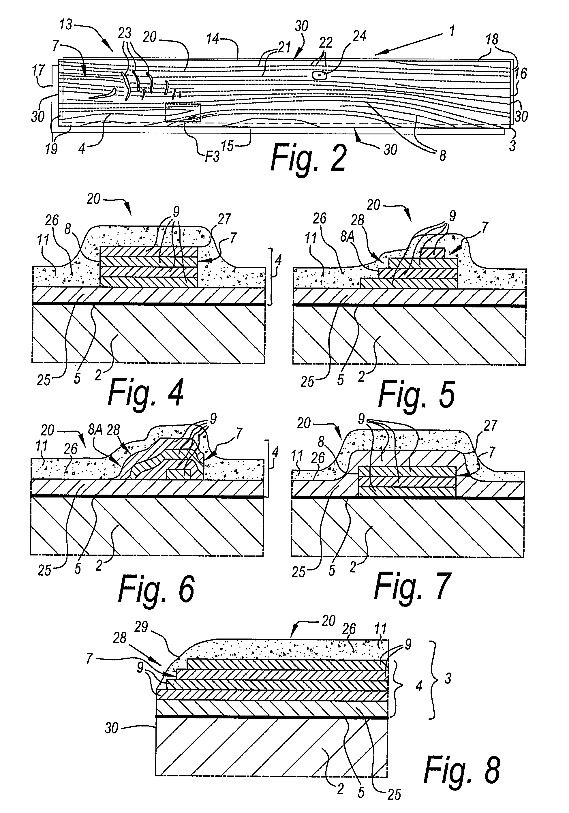
[0033]FIG. 1 shows an example method for manufacturing a coated panel 1. Herein, one starts from a board-shaped substrate 2, on which a decorative top layer 3 is provided. For forming the top layer 3, the method involves at least a step S1 in which the substrate 2 is printed. The print 4 from step S1 represented here is performed indirectly on the substrate 2. In a preceding step S0, this substrate 2 then has been provided with one or more primer layers 5, such as uniform basic layers. Providing this basic layer or primer layer 5 in step S0 comprises, in this example, at least providing a substance 6, such as a lacquer, in liquid form. According to another possibility, the basic layer may also comprise solid layers, such as paper layers, or one may work without basic layer, such that in this latter case the print 4 is performed directly on the substrate 2.

[0034]The particularity of the method of the example consists in that during said step S1, in which the substrate 2 is printed, a...


PUM


Abstract

A coated panel may include a substrate and a decorative top layer provided on the substrate. A method for manufacturing the panel may involve forming at least a portion of the top layer by printing on the substrate to provide a structure on the substrate. The structure may include protrusions formed by two or more prints provided on top of each other.

Description

PRIORITY STATEMENT[0001]This US non-provisional application claims priority under 35 USC §119 to European Patent Application No. 08006954.5 filed Apr. 8, 2008, the content of which is incorporated herein in its entirety by reference.BACKGROUND[0002]1. Field of the invention[0003]In general, the invention relates to a method for manufacturing coated panels, as well as to coated panels. More particularly, the invention relates to a method for manufacturing panels of the type comprising at least a substrate and a decorative top layer provided on this substrate, wherein the method, in order to form at least a portion of the top layer, comprises a step in which the substrate is printed, whether or not by the intermediary of possible primer layers or other intermediate material, in particular intermediate material layers.[0004]2. Description of Related Art[0005]Panels are known, for example, from the patent documents U.S. Pat. No. 3,173,804, U.S. Pat. No. 3,554,827, U.S. Pat. No. 3,811,91...

Claims


Application Information

Patent Timeline
Patent Type & Authority Patents(United States)
IPC IPC(8): B05D1/36B05D5/00
CPCB44C3/025B44F9/02B44C5/043Y10T428/24438
Inventor PROVOOST, PETERVERHAEGHE, BART
Owner FLOORING IND LTD
Why Eureka
Try Eureka