Dual magnet hall effect switch

a dual-magnet, hall-effect switch technology, applied in the direction of galvano-magnetic hall-effect devices, pulse techniques, galvano-magnetic devices, etc., can solve the problems of thermal effects, alter the magnetic field or the sensitivity of the switch,

Inactive Publication Date: 2005-03-15
OTTO CONTROLS DIV OTTO ENG
View PDF15 Cites 64 Cited by
  • Summary
  • Abstract
  • Description
  • Claims
  • Application Information

AI Technical Summary

Benefits of technology

The present invention provides a dual magnet Hall effect switch for contactless switching. The Hall effect switch includes a an internal housing positioned inside an external housing. Inside the internal housing is a magnet carriage having two magnets, a return spring, a Hall effect sensor and a clicker ball. The two magnets are positioned in contact with each other and with opposite polarities facing the Hall effect sensor. When the switch is actuated, the magnet carriage is displaced relative to the Hall effect sensor. The resulting displacement of the two magnets within the magnet carriages alters the magnetic field detected by the Hall effect sensor. When the magnetic field detected by the Hall effect sensor reaches a certain predetermined level the switch is actuated.

Problems solved by technology

For example, the mechanical contacts in a conventional switch may become corroded with use or alternatively the contacts may no longer form an acceptable electrical connection with use, Hall effect switches may be durable up to millions of actuations.
Also, thermal effects may be encountered in some applications and may alter a switch's magnetic field or the sensitivity of the switch's Hall effect probe.

Method used


Image

  • Dual magnet hall effect switch
  • Dual magnet hall effect switch
  • Dual magnet hall effect switch

Examples


Embodiment Construction

In the following detailed description, spatially orienting terms are used such as “left”, “right”, “vertical”, “horizontal”, and the like. It is to be understood that these terms are used for convenience of description of the preferred embodiments by reference to the drawings. These terms do not necessarily describe the absolute location in space, such as left, right, upward, downward, etc., that any part must assume.

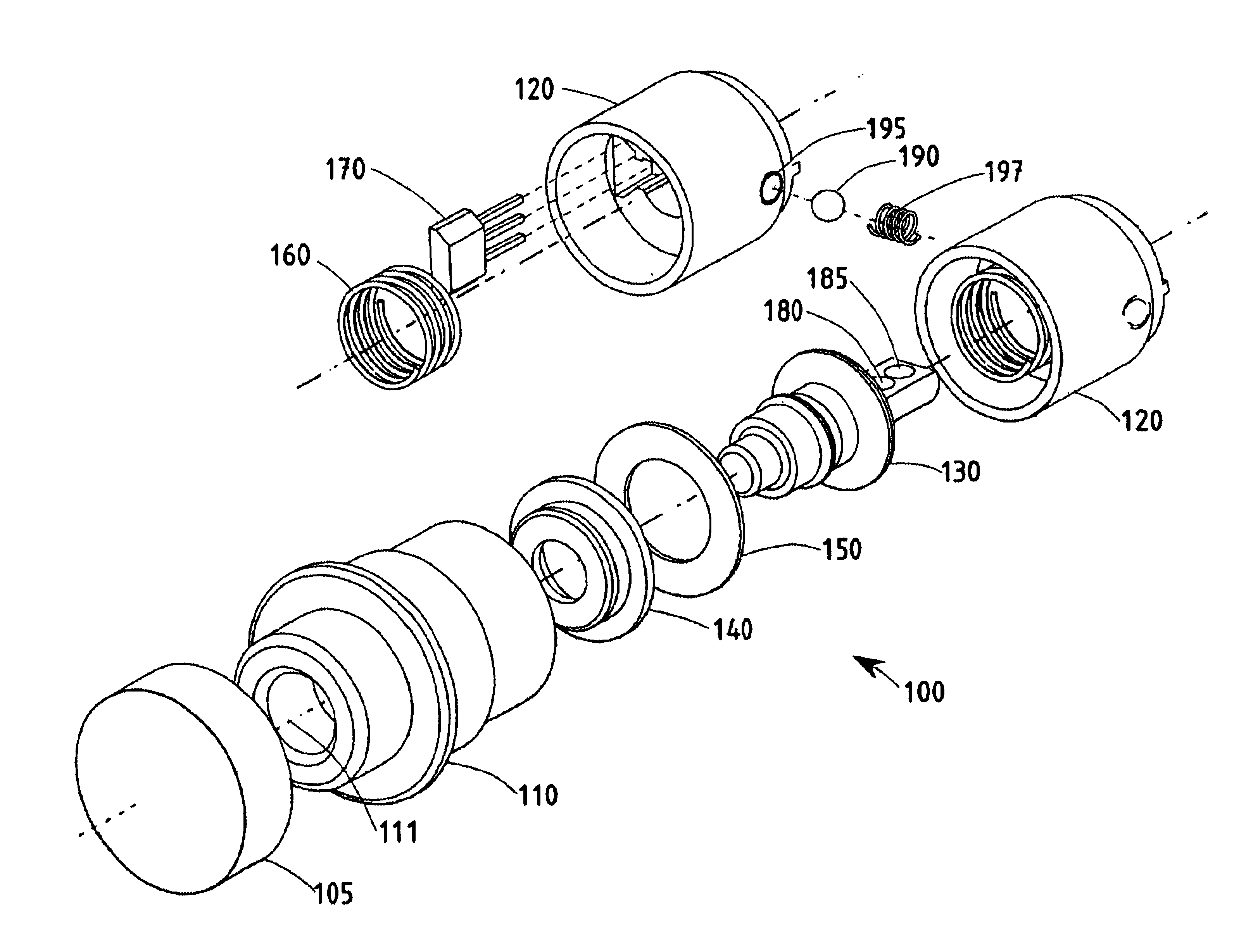
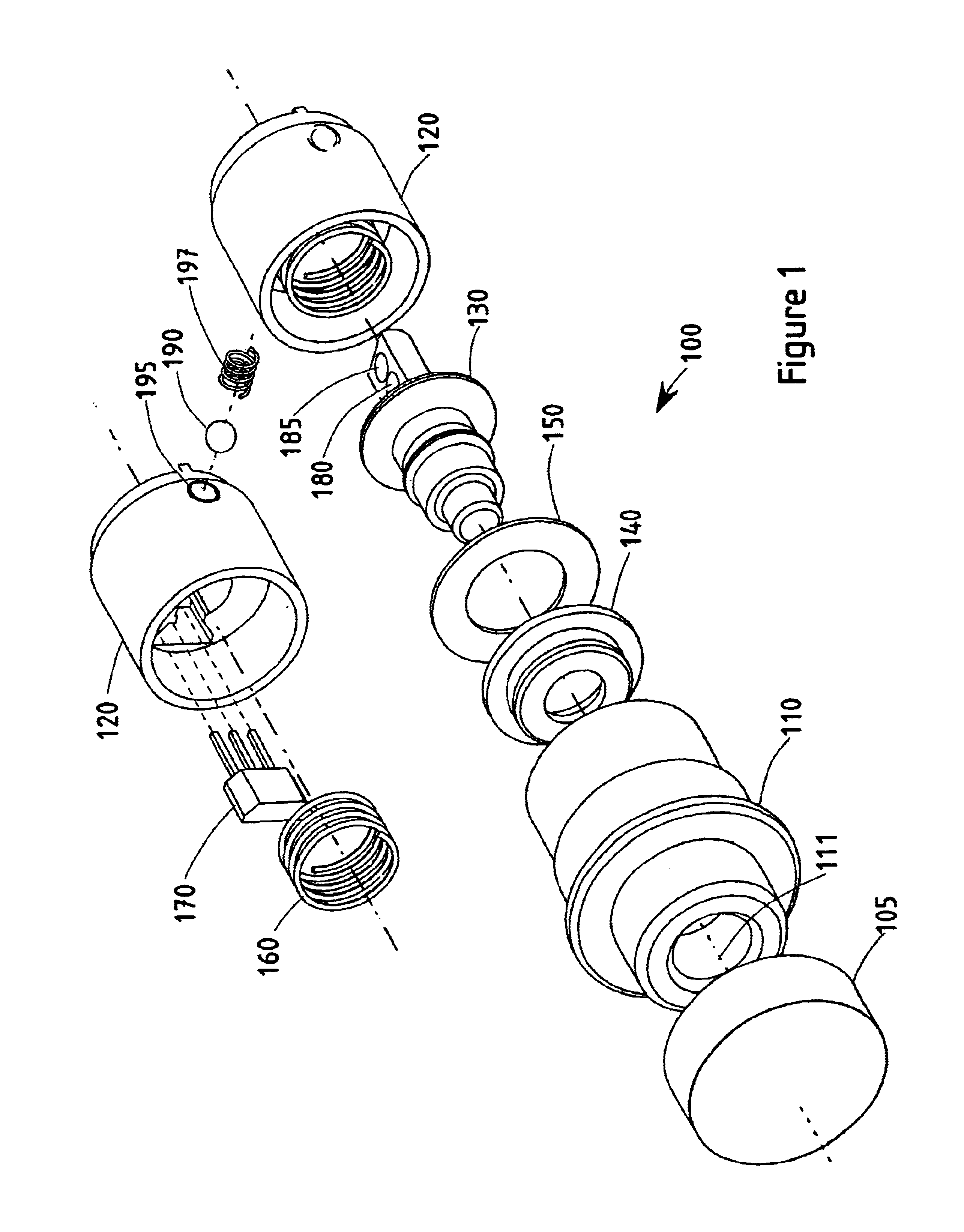
FIG. 1 illustrates the individual components of a push button dual magnet Hall effect switch 100 according to a preferred embodiment of the present invention. The switch 100 includes an end cap 105, exterior housing 110 having an axis 111, an interior housing 120, a magnet carriage 130, a boot seal 140, a seal washer 150, a return spring 160, a Hall effect sensor 170, an first magnet 180, a second magnet 185, a clicker ball 190, a clicker ball aperture 195, and a clicker ball spring 197.

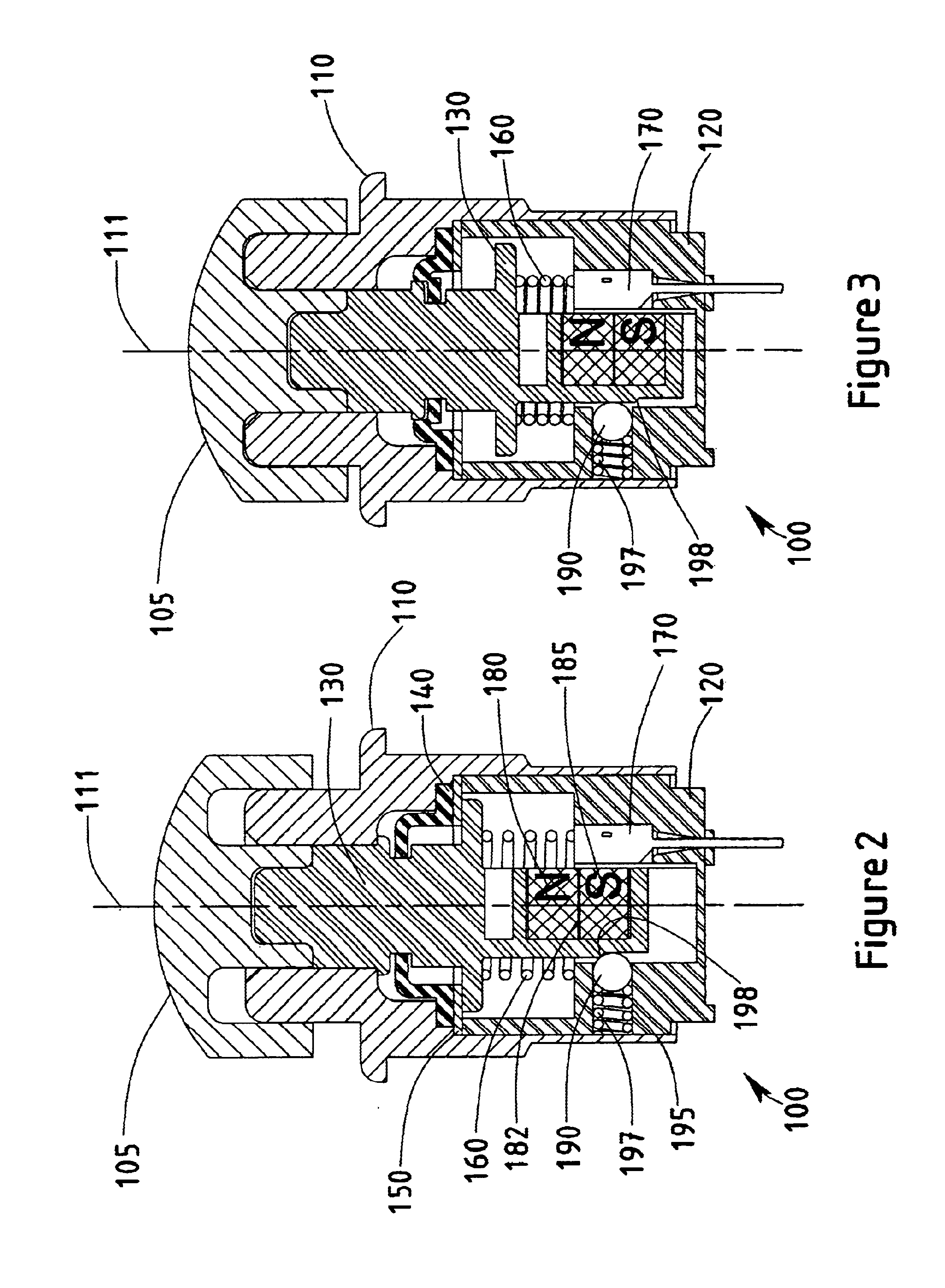
FIG. 2 illustrates the assembled push button dual magnet Hall effect switch 100 of F...


PUM


Abstract

A dual magnet Hall effect switch for contactless switching is provided. The Hall effect switch includes a magnet carriage and a Hall effect sensor positioned inside a switch housing. The magnet carriage includes two magnets positioned with opposite polarities facing the Hall effect sensor and in contact. When the switch is actuated, the magnet carriage is displaced within the switch housing and relative to the Hall effect sensor. The two magnets positioned inside the magnet carriage are also displaced. The positional displacement of the magnets relative to the Hall effect sensor alters the magnetic field detected by the Hall effect sensor. When the magnetic field detected by the Hall effect sensor reaches a predetermined level, the switch is actuated. The Hall effect switch also includes a boot seal sealing the switch and an internal clicker ball to provide an audible or tactile indication of the switch's actuation.

Description

BACKGROUND OF THE INVENTIONThe present invention generally relates to a dual magnet Hall effect switch. More particularly, the present invention relates to a push button, dual magnet Hall effect switch wherein the two magnets are aligned in parallel, in contact, and have opposite polarities.The Hall effect occurs when charge carriers moving through a material experience a deflection because of an applied magnetic field. The deflection of the charge carriers results in a measurable electrical potential difference across the material. The potential difference is transverse to the magnetic field and the current direction. A Hall effect transducer measures the applied magnetic field and converts that measurement into a voltage. Hall effect transducers may be packaged to form commercially available Hall effect probes.Many common applications may rely on the Hall effect and Hall effect probes. For instance, some computer keyboards employ a small magnet and a Hall effect probe to detect wh...

Claims


Application Information

Patent Timeline
Patent Type & Authority Patents(United States)
IPC IPC(8): H03K17/94H03K17/97
CPCH03K17/97
Inventor KULLE, ROGER K.
Owner OTTO CONTROLS DIV OTTO ENG
Why Eureka
Try Eureka