Injection foam molding method and apparatus therefor

Inactive Publication Date: 2011-12-15
PRIME POLYMER CO LTD
View PDF2 Cites 6 Cited by
  • Summary
  • Abstract
  • Description
  • Claims
  • Application Information

AI Technical Summary

Benefits of technology

[0091]As described above, in this exemplary embodiment, the following advantages can be attained.
[0092]In this exemplary embodiment, after gas is introduced into the cavity 113 formed by clamping the die to boost pressure therein, the resin material X, which is the thermoplastic resin containing the foaming agent, is injected to form the skin layer. Subsequently, at the same time as the start of the core back or after the elapse of a predetermined time from the start of the core back, the gas in the cavity 113 is vacuum-suctioned to make the pressure in the cavity 113 less than the atmospheric pressure and the resin material X is cooled and solidified.
[0093]Thus, since the gas is vacuum-suctioned before the resin material X is completely solidified, the gas between the resin material X and an inner surface of the die 110 is reliably discharged out of the cavity 113, which relia

Problems solved by technology

However, in the method disclosed in Patent Literature 1 that the pressurizing gas is discharged while the cavity partially remains unfilled, a so-called swirl mark is generated at a part corresponding to an unfilled part of an injection foam molded article, thereby impairing its appearance.
However, in the method for preventing an increase in the internal pressure in the cavity as disclosed in Patent Literature 2, a gas pressure in the cavity is set at 0 p

Method used


Image

  • Injection foam molding method and apparatus therefor
  • Injection foam molding method and apparatus therefor
  • Injection foam molding method and apparatus therefor

Examples


Example

Example 1

(1) Manufacturing Machine

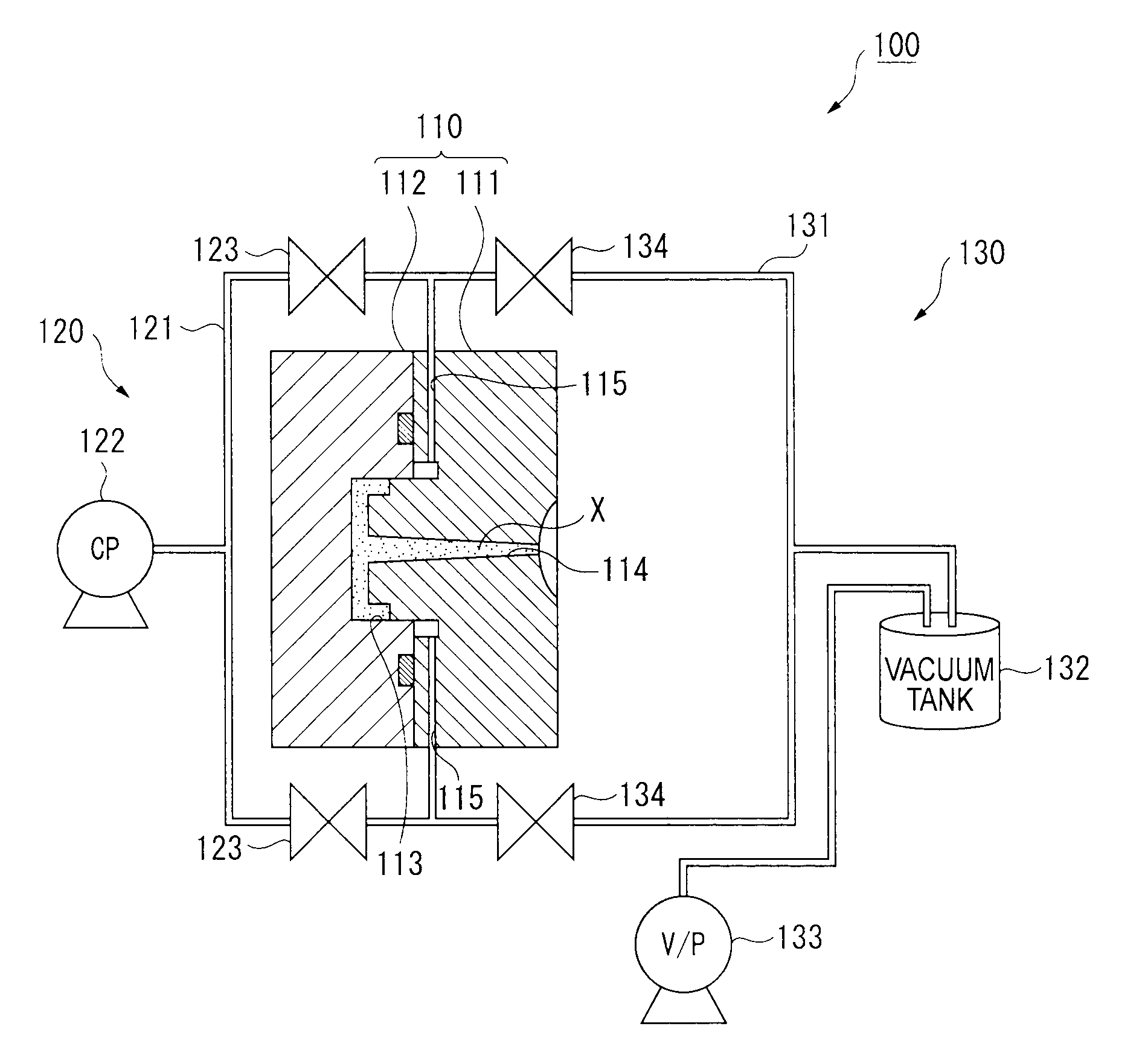
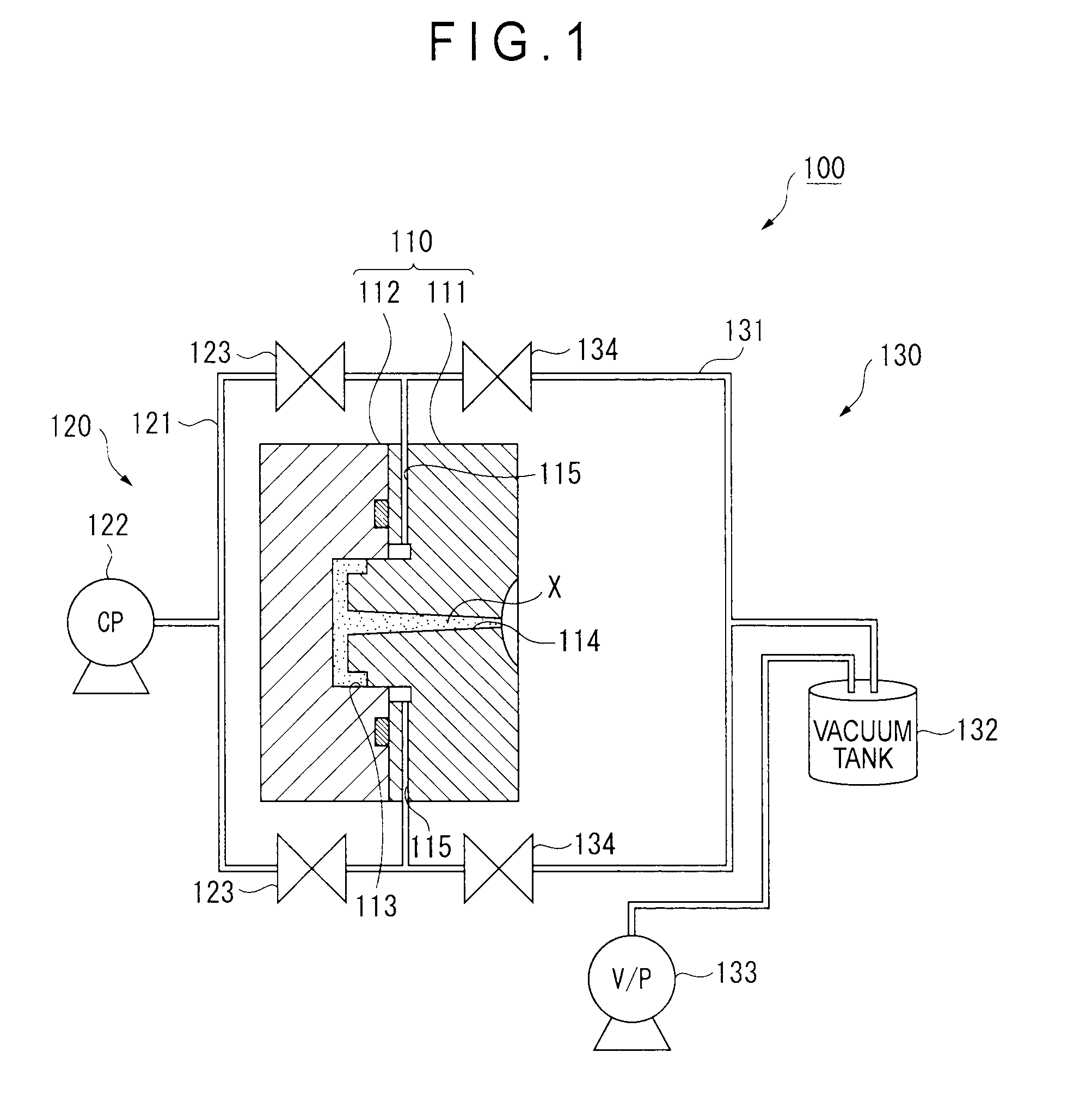
[0113]A die having a cavity size of 850×450 mm was used for obtaining an injection foam molded article shaped like a door trim, as shown in FIG. 1. The die was adjusted such that a thickness of the cavity when the die was completely closed became 1.6 mm.

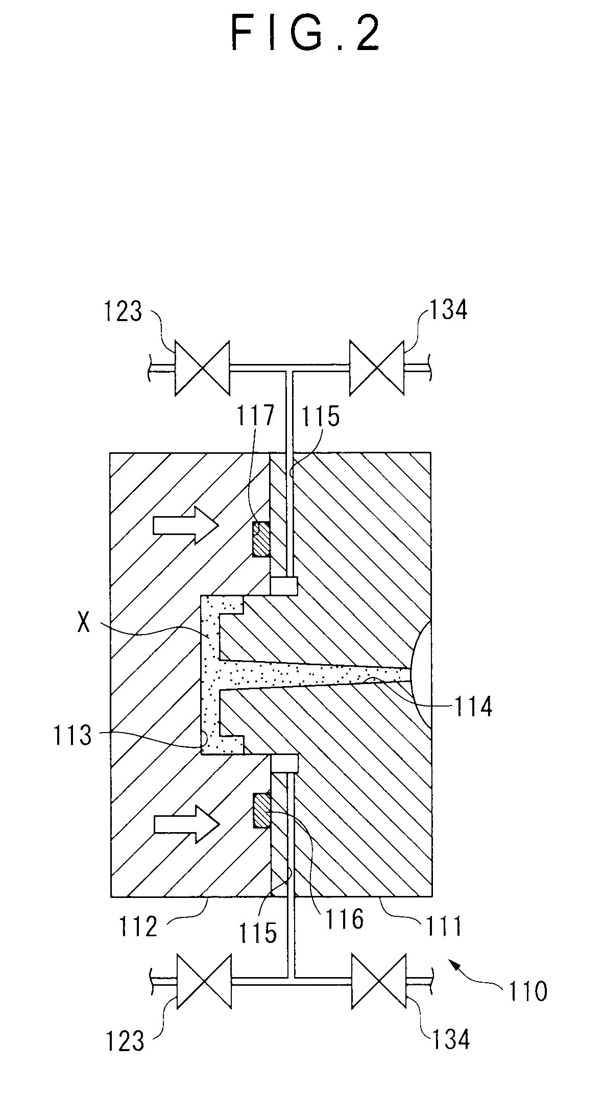
[0114]The periphery of the cavity in the die forms a shear edge structure. A looped gas flow path having a width of 5 mm and a height of 15 mm was provided in an outer circumference near a base end of a convex portion in the fixed die. The gas flow path was interconnected to the cavity through a gap of the shear edge. A rubber seal member (an O-ring) was further provided in an outer circumference of the gas flow path. Accordingly, gas sealing in the cavity and the gas flow path was attained by bringing the movable die and the seal member into contact with each other in a die-clamped state.

[0115]The gas flow path was also connected to the booster and the vacuum suction device as shown in FIGS. 1 and 2...

Example

Examples 2 to 5, Comparisons 1 to 6

[0122]An injection foam molded article was obtained in the same manner as in Example 1 except for the added amount of CO2, the internal pressure of the cavity, the timing of gas discharging (time from completion of the injection to vacuum suction), the status of performance of vacuum suction and the vacuum degree, which are shown in Tables 1 and 2.

[0123]A saturation solubility pressure in each of Examples 2 and 3 and Comparisons 1 to 4 was the same as that in Example 1. A saturation solubility pressure in each of Example 4 and Comparison 5 was 0.42 MPa. A saturation solubility pressure in each of Example 5 and Comparison 6 was 0.31 MPa.

Evaluation

[0124]Generation of swirl marks and presence / absence of dimpled or amorphous recesses on a surface of the obtained injection foam molded article were visually observed and evaluated on the following three scales. Results are shown in Tables 1 and 2 below.

[0125]A: absence of swirl marks or recesses

[0126]B:...


PUM

PropertyMeasurementUnit
Timeaaaaaaaaaa
Pressureaaaaaaaaaa
Timeaaaaaaaaaa

Abstract

After introducing gas into a cavity of a clamped die to boost a pressure therein, a resin material containing a foaming agent is injected. After forming a skin layer, at the same time as a start of a core-back operation for foaming the resin material or after the core-back operation, gas in the cavity is vacuum-suctioned to make a pressure in the cavity less than the atmospheric pressure. By cooling and solidifying, an injection foam molded article is obtained. Before complete solidification, gas between the resin material and an inner surface of the die is reliably discharged out of the cavity, so that surface recesses and generation of swirl marks due to gas accumulation can be prevented.

Description

TECHNICAL FIELD[0001]The present invention relates to an injection foam molding method for forming an injection foam molded article by injecting a thermoplastic resin containing a foaming agent, and an apparatus thereof.BACKGROUND ART[0002]Injection foam molded articles have typically been used as, for instance, a door trim and the like in automobiles. Various methods have been known as an injection foam molding method for providing such injection foam molded articles (see, for instance, Patent Literatures 1 to 3).[0003]In an injection foam molding method disclosed in Patent Literature 1, when a molten resin is fed in a cavity pressurized with a pressurizing gas, the gas in an unfilled part of the cavity is discharged and vacuum-suctioned, thereby instantly reducing pressure and facilitating filling of the molten resin.[0004]However, in the method disclosed in Patent Literature 1 that the pressurizing gas is discharged while the cavity partially remains unfilled, a so-called swirl m...

Claims


Application Information

Patent Timeline
IPC IPC(8): B29C44/42
CPCB29C44/586
Inventor OBARA, TOMOYUKI
Owner PRIME POLYMER CO LTD
Why Eureka
Try Eureka