Motorcycle

a technology for motorcycles and motors, applied in the field of motorcycles, can solve the problems of reducing the accuracy of the control of the shift spindle by the actuator, difficult to achieve the smooth shifting operation, and heat and vibration generated by the engine to be conducted, so as to ensure durability, stable operation, and easy attachment

Inactive Publication Date: 2006-05-11
YAMAHA MOTOR CO LTD
View PDF6 Cites 13 Cited by
  • Summary
  • Abstract
  • Description
  • Claims
  • Application Information

AI Technical Summary

Benefits of technology

[0011] In order to overcome the problems described above, preferred embodiments of the present invention provide a motorcycle that has a

Problems solved by technology

However, in this conventional motorcycle, the provision of the shift actuator and clutch actuator near the engine allows direct cause heat and vibrations generated by the engine to be conducted to the actuators.
However, when heat and vibrations are applied to the actuator, temperature and pressure variations of the operating oil and vibrations of mechanical components vary the timing and amount by which the actuator drives the shift spindle, which lowers the accuracy of the control of the shift spindle by the actuator.
This makes it difficult to achieve the shifting operation smoothly.
Also

Method used


Image

  • Motorcycle
  • Motorcycle
  • Motorcycle

Examples


first preferred embodiment

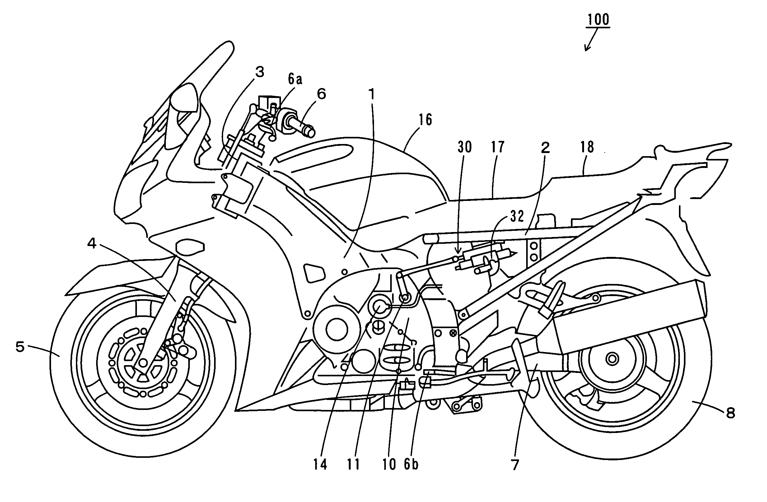
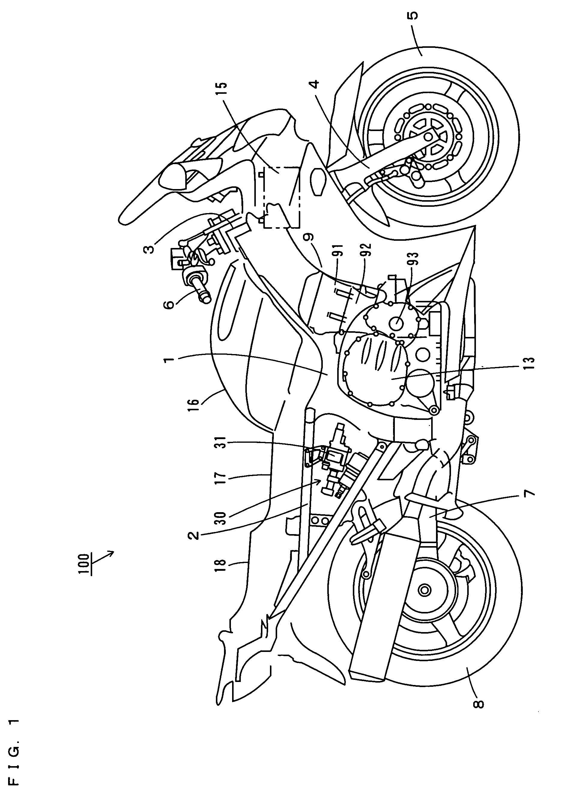
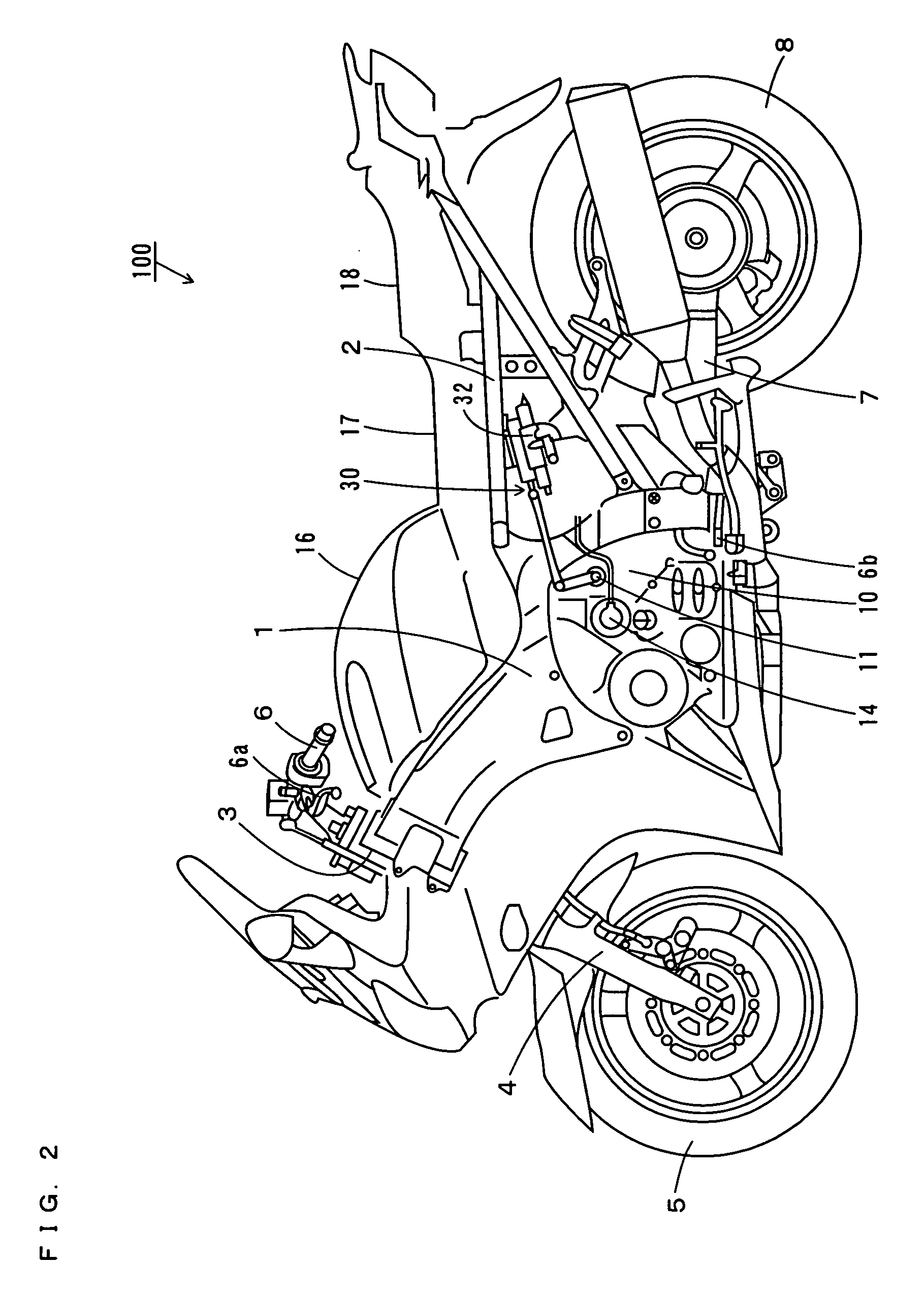
[0054]FIG. 1 is a right-side view of a motorcycle according to a first preferred embodiment of the present invention, FIG. 2 is a left-side view of the motorcycle, and FIG. 3 is a plan view of the motorcycle as seen from above.

[0055] As shown in FIGS. 1 and 2, the motorcycle 100 has a main frame 1. A sub-frame 2 is attached to the rear end of the main frame 1 and extends rearward.

[0056] The main frame 1 is provided with a head pipe 3 at its front end. The head pipe 3 is provided with a front fork 4 that can swing left and right. A front wheel 5 is rotatably supported at the lower end of the front fork 4. A handle 6 is attached to the top end of the head pipe 3.

[0057] A rear arm 7 is disposed to extend rearward from below the main frame 1. A rear wheel 8 is rotatably supported at the rear end of the rear arm 7.

[0058] An engine 9 is held in a center portion of the main frame 1. The engine 9 includes a cylinder head 91, a cylinder block 92, and a crankshaft 93. As shown in FIG. 2, ...

second preferred embodiment

[0100]FIG. 8 is a left-side view showing the details of a sub-frame and an AMT mechanism of a motorcycle according to a second preferred embodiment of the present invention, and FIG. 9 is a plan view showing the details of the sub-frame and the AMT mechanism of the motorcycle.

[0101] The motorcycle of the present preferred embodiment differs from the motorcycle 100 of the first preferred embodiment in that the AMT mechanism 30 includes an electrically-driven clutch actuator 61 and an electrically-driven shift actuator 62 in place of the hydraulic clutch actuator 31 and the hydraulic shift actuator 32.

[0102] The clutch actuator 61 and the shift actuator 62 are attached to the sub-frame 2.

[0103] As shown in FIG. 9, the clutch actuator 61 has an electric motor 611, a gearbox 612, and a master cylinder 613. The shift actuator 62 has an electric motor 621 and a gearbox 622.

[0104] The clutch actuator 61 is disposed between the main support member 21 on the right side and the main suppo...


PUM


Abstract

A sub-frame of a motorcycle is attached to the rear end of a main frame of the motorcycle and extends rearward. An AMT (Automated Manual Transmission) mechanism is attached to the sub-frame which prevents direct conduction of heat and vibrations generated by an engine on the main frame to the AMT. The AMT mechanism includes a hydraulic clutch actuator, a hydraulic shift actuator, an accumulator, a valve block, a pump, and an oil tank.

Description

BACKGROUND OF THE INVENTION [0001] 1. Field of the Invention [0002] The present invention relates to a motorcycle that has a clutch driving device for driving a clutch and a shift driving device for driving a transmission. [0003] 2. Description of the Background Art [0004] The AMT (Automated Manual Transmission) mechanism is conventionally proposed as a system that automates the switching (shifting) of the gear ratio of the transmission of a motorcycle and the connecting and disconnecting of the clutch. The AMT mechanism involves a shift actuator for driving the transmission and a clutch actuator for driving the clutch (see JP 2003-320861A). [0005] In the motorcycle having the AMT mechanism disclosed in JP 2003-320861A, the shift actuator and the clutch actuator are positioned behind the cylinder block of the engine and above the transmission. Positioning the actuators near the engine in this way prevents the actuators from touching the ground during cornering of the motorcycle. Thi...

Claims


Application Information

Patent Timeline
IPC IPC(8): B62M7/00B62M25/00F16D25/08F16H61/28
CPCB62M25/00
Inventor YAMADA, MASAICHISUZUKI, TAKAHIRONOZAKI, HIROSHIFUKUSHIMA, KENJI
Owner YAMAHA MOTOR CO LTD
Why Eureka
Try Eureka