AI technical title is built by Patsnap AI team. It summarizes the technical point description of the patent document.
a frame and snowmobile technology, applied in the field of snowmobile frame construction, can solve the problems of inconvenient transfer and significant addition of vehicle weight, and achieve the effect of convenient and convenient transfer
Inactive Publication Date: 2006-05-25
BOMBARDIER RECREATIONAL PROD INC
View PDF35 Cites 14 Cited by
Summary
Abstract
Description
Claims
Application Information
AI Technical Summary
This helps you quickly interpret patents by identifying the three key elements:
Problems solved by technology
Method used
Benefits of technology
Benefits of technology
[0010] In view of the foregoing, one object of the present invention is to exploit the design elements of a snowmobile that are easily and readily transferred to the design of an ATV based on the same basic frame structure.
[0015] It is a further object of the present invention to provide a foot-gripping element on a footrest that includes a jagged portion extending upwardly from the footrest and defining teeth at a top portion thereof. A deflector portion is positioned at an opposite side of a hole through the footrest and is angled downwardly from the footrest to discourage particles from being stirred up and passing through the hole onto a top portion of the footrest.
[0016] It is still another object of the present invention to incorporate a heat exchanger into the tunnel. In an alternate embodiment, the heat exchanger is a radiator that extends substantially the length of the tunnel and assists in dissipating heat from engine coolant circulating therethrough.
Problems solved by technology
Despite this, snowmobiles, ATVs, and other recreational vehicles do not share a common design approach or a commonality of components.
Unfortunately, this adds significantly to the overall weight of the vehicle.
A problem with this construction technique is that the holes may not line up as precisely as the manufacturer would like.
Method used
Image
Click on the blue label to locate the original text in one second.
Reading with bidirectional positioning of images and text.
Examples
Embodiment Construction
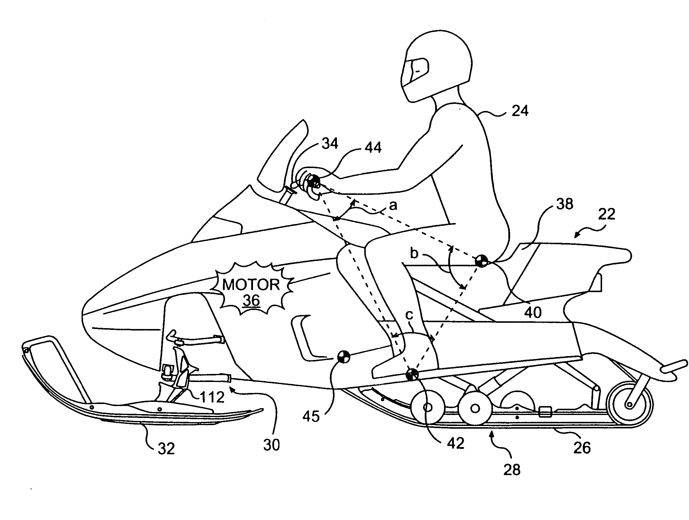
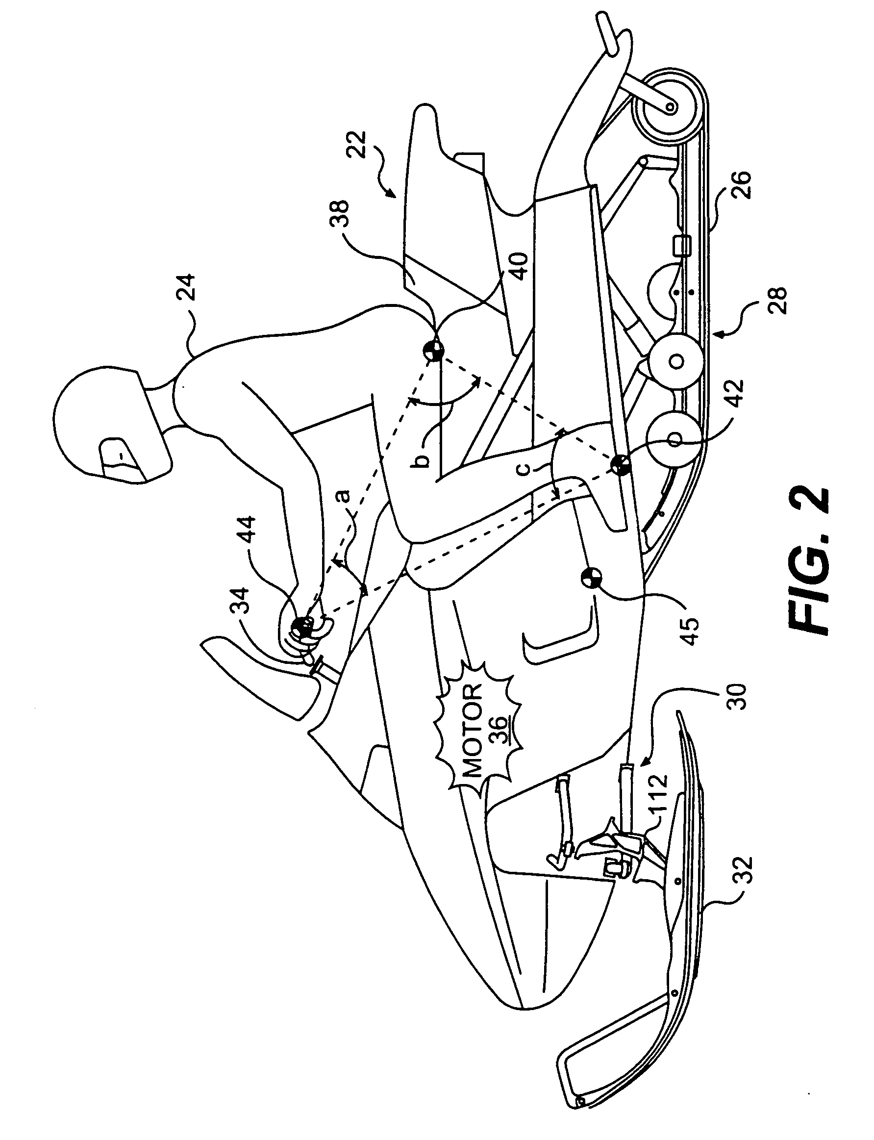
[0058] Before delving into the specific details of the present invention, it should be noted that the conventions “left,”“right,”“front,”“forward”, “upward”, “downward” and “rear” are defined according to the normal, forward travel direction of the vehicle being discussed. As a result, the “left” side of a snowmobile is the same as the left side of the rider seated in a forward-facing position on the vehicle (or travelling in a forward direction on the vehicle).
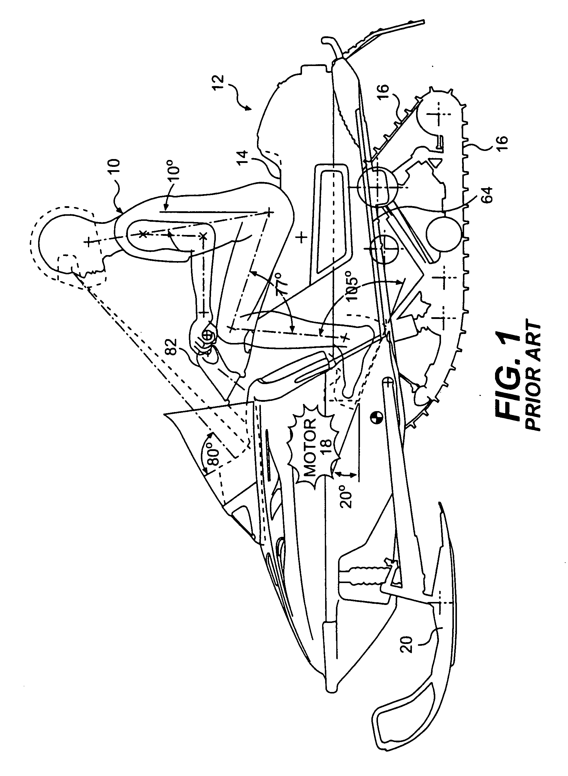
[0059]FIG. 1 illustrates a rider operator 10 sitting on a prior art snowmobile 12. Rider 10 is positioned on seat 14, with his weight distributed over endless track 16. Motor 18 (shown in general detail) is located over skis 20. As with any snowmobile, endless track 16 is operatively connected to motor (or engine) 18 to propel snowmobile 12 over the snow. Motor or engine 18 typically is a two-stroke internal combustion engine. Alternatively, a 4-stroke internal combustion engine may be substituted therefor. In addition, any ...
PUM
Abstract
A snowmobile frame includes a tunnel, the tunnel includes a left side structure having a front portion and a rear portion, a right side structure having a front portion and a rear portion, a radiator interconnecting the rear portion and the left side structure with the rear portion of the right side structure, and an engine cradle forward of the tunnel. The engine cradle includes a front wall connecting the front portion of the left side structure and the front portion of the right side structure, a rear wall interconnecting the left side structure and the right side structure, and a bottom plate intermediate the front wall and the rear wall and interconnecting the left side structure with the right side structure. A snowmobile including the snowmobile frame includes an engine and a fastener passing through a hole in one of the left side structure and the right side structure to fasten the engine thereto.
Description
CROSS REFERENCE TO RELATED APPLICATIONS [0001] This is a continuation of U.S. application Ser. No. 10 / 141,135, filed May 9, 2002, which is a divisional of U.S. application Ser. No. 09 / 877,064, filed Jun. 11, 2001, which claims priority to U.S. Application 60 / 246,110, filed Nov. 7, 2000, the entire contents of all of which are incorporated herein by reference. This application is a continuation-in-part of U.S. application Ser. No. 09 / 472,133, filed Dec. 23, 1999, the contents of which are incorporated herein by reference, which claims priority to Canadian Patent Application 2,256,944, filed Dec. 23, 1998, the contents of which are also incorporated herein by reference. This application also incorporates by reference U.S. Application Ser. No. 09 / 472,134, filed Dec. 23, 1999. In addition, this application incorporates by reference U.S. Application 60 / 230,432, filed Sep. 6, 2000. Finally, this application claims priority to U.S. Application 60 / 237,384, filed Oct. 4, 2000, the contents o...
Claims
Application Information
Patent Timeline
Application Date:The date an application was filed.
Publication Date:The date a patent or application was officially published.
First Publication Date:The earliest publication date of a patent with the same application number.
Issue Date:Publication date of the patent grant document.
PCT Entry Date:The Entry date of PCT National Phase.
Estimated Expiry Date:The statutory expiry date of a patent right according to the Patent Law, and it is the longest term of protection that the patent right can achieve without the termination of the patent right due to other reasons(Term extension factor has been taken into account ).
Invalid Date:Actual expiry date is based on effective date or publication date of legal transaction data of invalid patent.
Patent Type & AuthorityApplications(United States)

