Front suspension with three ball joints for a vehicle

a front suspension and ball joint technology, applied in the field of vehicles, can solve the problems of not providing a simple front suspension construction, the design approach of the front suspension has not been common, and the addition of additional components adds to the manufacturing cost and the complexity of snowmobiles, so as to achieve the effect of easy and quick transfer

Inactive Publication Date: 2005-03-15
BOMBARDIER RECREATIONAL PROD INC
View PDF39 Cites 49 Cited by
  • Summary
  • Abstract
  • Description
  • Claims
  • Application Information

AI Technical Summary

Benefits of technology

In view of the foregoing, one object of the present invention is to exploit the design elements of a snowmobile that are easily and readily transferred to the design of a wheeled vehicle, such as an ATV, based on a basic frame structure.
To that end, one object of the present invention is to provide a front suspension that incorporates a double A-arm construction which does not require a heavy, front leg with a steering shaft disposed therein.

Problems solved by technology

Despite this, snowmobiles, ATVs, wheeled vehicles, and other recreational vehicles do not share a common design approach or a commonality of components.
For example, there has not been a common design approach to the front suspensions that are incorporated into snowmobiles, ATVs, and other wheeled vehicles even though there are common design parameters for each of these types of vehicles.
While both of these front suspensions provide adequate control and steering of the respective snowmobiles on which they are installed, neither provides a simple construction for a front suspension.
The additional components add to the manufacturing cost and to the complexity of snowmobile 12.
Moreover, the additional components increase the overall weight of snowmobile 12.
In this case, however, the complexity of the system and the weight of the components are particularly pronounced.
All of this adds considerably to the overall weight and construction cost of snowmobile 460.
No prior art front suspension, however, offers or suggests a practicable approach.

Method used


Image

  • Front suspension with three ball joints for a vehicle
  • Front suspension with three ball joints for a vehicle
  • Front suspension with three ball joints for a vehicle

Examples


Embodiment Construction

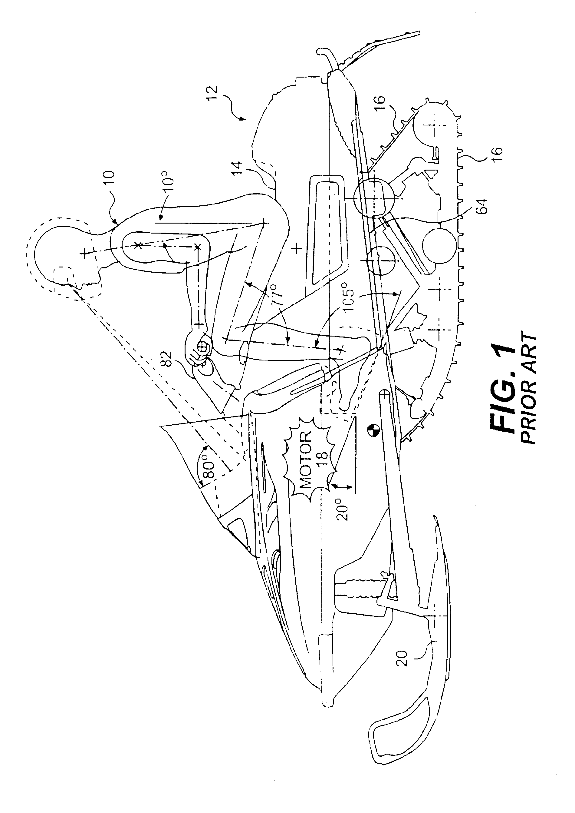
Before delving into the specific details of the present invention, it should be noted that the conventions “left,”“right,”“front,” and “rear” are defined according to the norm al, forward travel direction of the vehicle being discussed. As a result, the “left” side of a snowmobile is the same as the left side of the rider seated in a forward-facing position on the vehicle (or travelling in a forward direction on the vehicle).

FIG. 1 illustrates a rider operator 10 sitting on a prior art snowmobile 12. Rider 10 is positioned on seat 14, with his weight distributed over endless track 16. Motor 18 (shown in general detail) is located over skis 20. As with any snowmobile, endless track 16 is operatively connected to motor (or engine) 18 to propel snowmobile 12 over the snow. Motor or engine 18 typically is a two-stroke internal combustion engine. Alternatively, a 4-stroke internal combustion engine may be substituted therefor. In addition, any suitable engine may be substituted therefor....


PUM


Abstract

A suspension for a vehicle includes an upper A-arm and a lower A-arm. A leg with an axis is rotatably connected to both the upper A-arm and the lower A-arm. A mechanical link is rotatably connected to the leg so that movement of the mechanical link applies rotational force to the leg to cause the leg to rotate about the axis.

Description

1. Field of the InventionThe present invention concerns generally concerns the construction of vehicles such as snowmobiles, all terrain vehicles (“ATVs”), and other similar vehicles. More specifically, the present invention concerns the construction of a front suspension with three-ball joints that are connected to a support leg for the vehicle.2. Description of Related Art and General BackgroundSnowmobiles, ATVs, wheeled vehicles, and other related vehicles (hereinafter, “recreational vehicles,” although the appellation should not be construed to be limited only to the vehicles or type of vehicles described herein) often function under similar operating conditions. Despite this, snowmobiles, ATVs, wheeled vehicles, and other recreational vehicles do not share a common design approach or a commonality of components. This is due, in large part, to the different stresses and strains (mainly at the extremes) that the different vehicles experience during routine operation.As a general ...

Claims


Application Information

Patent Timeline
Patent Type & Authority Patents(United States)
IPC IPC(8): B62J35/00B62M27/02B62M27/00
CPCB62J35/00B62M27/02B62M2027/026
Inventor MALLETTE, BERTRANDGIROUARD, BRUNOFECTEAU, BERTHOLDCOTE, MARIO
Owner BOMBARDIER RECREATIONAL PROD INC
Why Eureka
Try Eureka