

Haptic panel apparatus
a technology of haptic panel and input, which is applied in the direction of instruments, computing, electric digital data processing, etc., can solve the problems of difficulty in recognizing that an input has been properly performed by the operator of the apparatus, and the inability of the visually impaired person to recognize that an inpu
- Summary
- Abstract
- Description
- Claims
- Application Information
AI Technical Summary
Problems solved by technology
Method used
Image


Examples
first embodiment
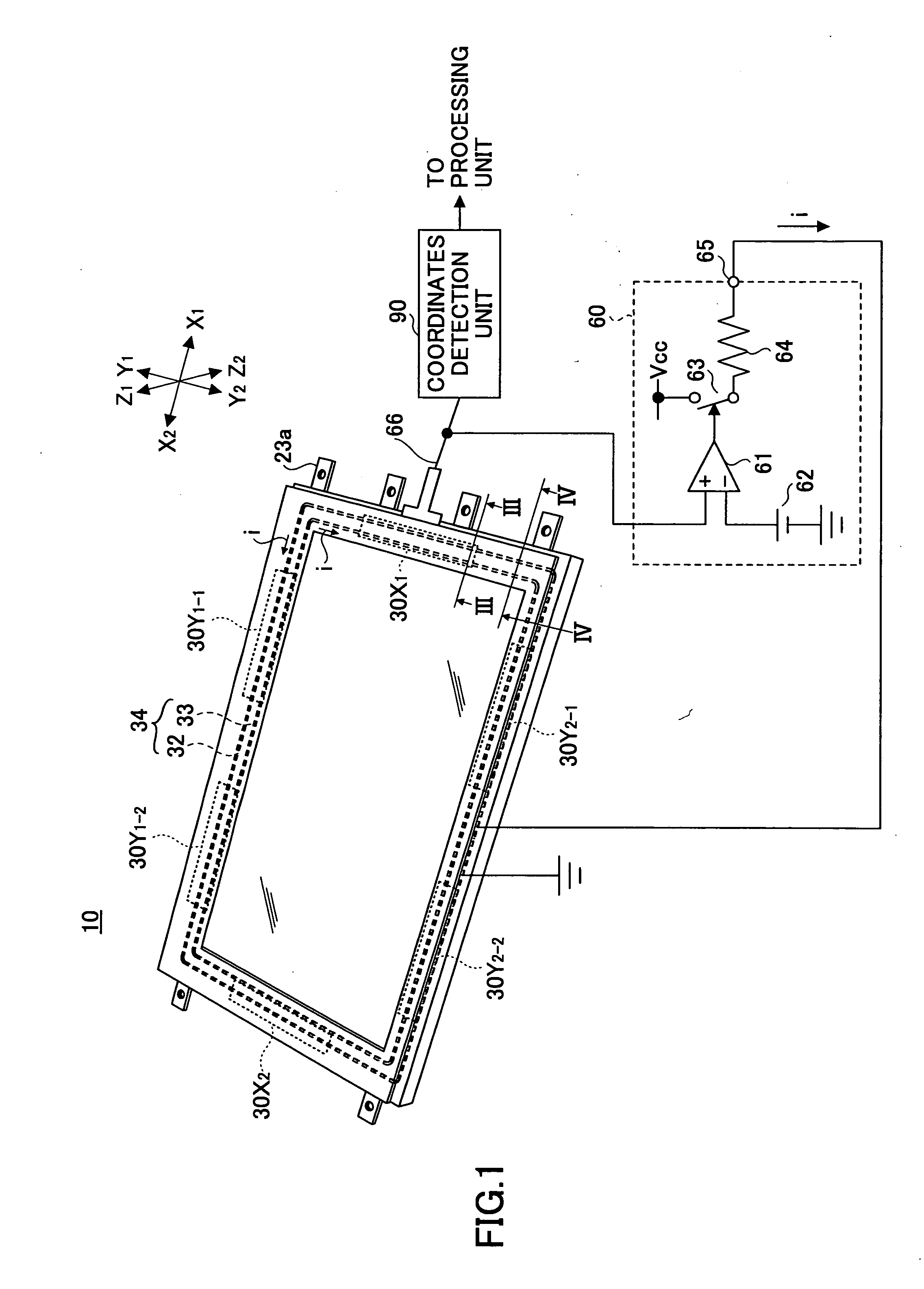
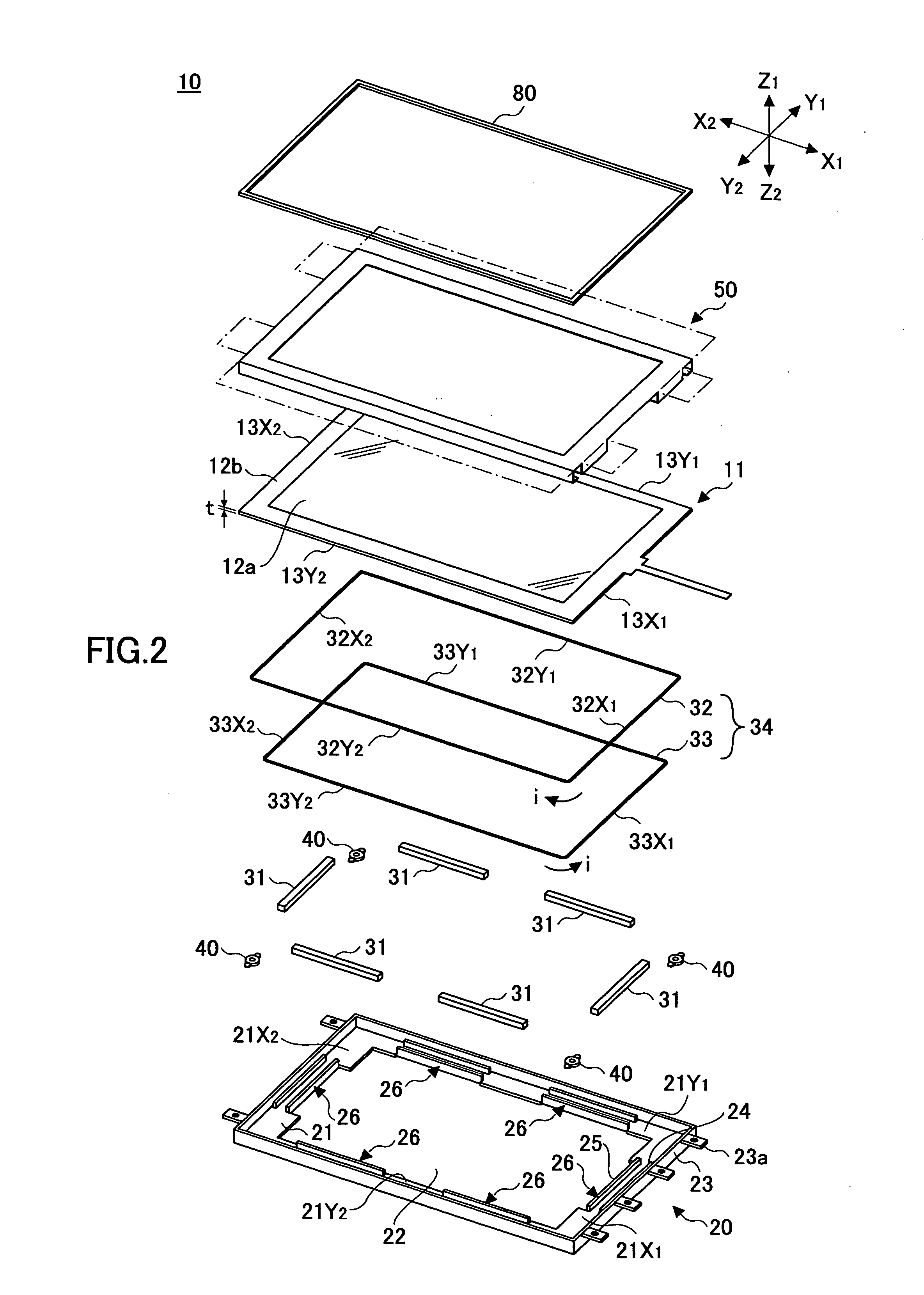
[0032] First, a structure of a haptic panel apparatus according to a first embodiment of the present invention is described.
[0033]FIG. 1 is a perspective view showing a structure of a haptic panel apparatus according to a first embodiment of the present invention. FIG. 2 is an exploded perspective view of the haptic panel apparatus of FIG. 1. FIG. 3 is a cross-sectional view showing a portion of the haptic panel apparatus of FIG. 1 across line III-III. FIG. 4 is a cross-sectional view of a portion of the haptic panel apparatus of FIG. 1 across line IV-IV. It is noted that FIGS. 3 and 4 show the states of the haptic panel apparatus being mounted into an equipment structure. FIGS. 5A˜5D are diagrams showing the structure of one of electromagnetic drive mechanisms of the haptic panel apparatus of FIG. 1. It is noted that in the above drawings, directions X1-X2 correspond to width directions, directions Y1-Y2 correspond to length directions, and directions Z1-Z2 correspond to depth dir...
second embodiment
[0065] In the following a haptic panel apparatus according to a second embodiment of the present invention is described.
[0066]FIG. 12 is an exploded perspective view of the haptic panel apparatus 10A according to the second embodiment. FIG. 13 is a cross-sectional view of a corner portion of the haptic panel apparatus 10A. FIGS. 14A and 14B are cross-sectional views of a section of the structure shown in FIG. 13. FIG. 15 is an exploded perspective view of the structure shown in FIG. 13.
[0067] It is noted that, aside from its corner portions, the haptic panel apparatus 10A of the second embodiment has a configuration generally identical to that of the haptic panel apparatus 10 of the first embodiment as is illustrated in FIGS. 1˜4. Accordingly, in FIG. 12, elements of the haptic panel apparatus 10A that are identical to those of the haptic panel apparatus 10 of FIG. 2 are assigned the same numerical references and their descriptions are omitted.
[0068] The haptic panel apparatus 10...
third embodiment
[0072] In the following a haptic panel apparatus according to a third embodiment of the present invention is described.
[0073]FIG. 16 is an exploded perspective view of the haptic panel apparatus 10B according to the third embodiment. FIG. 17 is a cross-sectional view of a corner portion of the haptic panel apparatus 10B. FIGS. 18A and 18B are cross-sectional views of a portion of the structure shown in FIG. 17. FIG. 19 is an exploded perspective view of a portion of the structure of FIG. 17.
[0074] According to the present embodiment, the electromagnetic drive mechanism 30 as is described in the previous embodiments is embedded into the tube member 100 as is described in relation to the second embodiment. It is noted that in FIGS. 16˜19, components that are identical to those shown in FIGS. 12˜15 are assigned the same numerical references.
[0075] As is shown in FIG. 16, a base member 20B of the haptic panel apparatus 10B of the present embodiment differs from the base member 20A of...
PUM
 Abstract
Description
Claims
Application Information