Modular fencing system and method for constructing same

Inactive Publication Date: 2006-06-01
ROYAL GROUP
View PDF28 Cites 53 Cited by
  • Summary
  • Abstract
  • Description
  • Claims
  • Application Information

AI Technical Summary

Problems solved by technology

One problem with current modular fencing systems is the manner in which the fencing components are interconnected.
Current s

Method used


Image

  • Modular fencing system and method for constructing same
  • Modular fencing system and method for constructing same
  • Modular fencing system and method for constructing same

Examples


Embodiment Construction

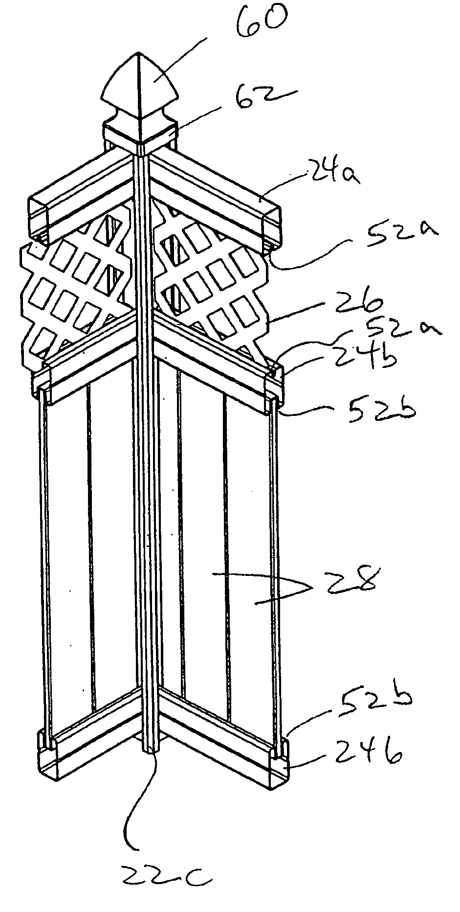
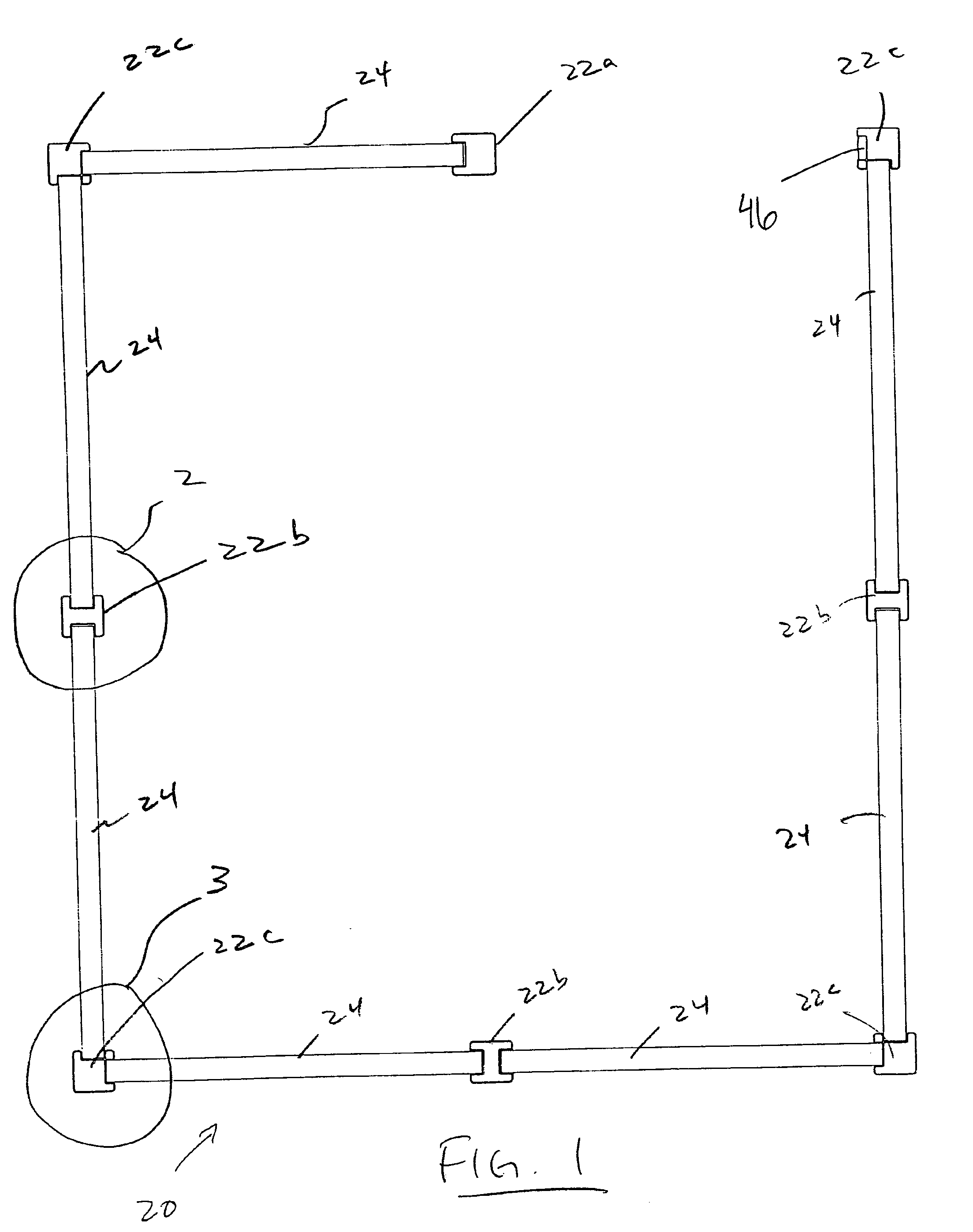
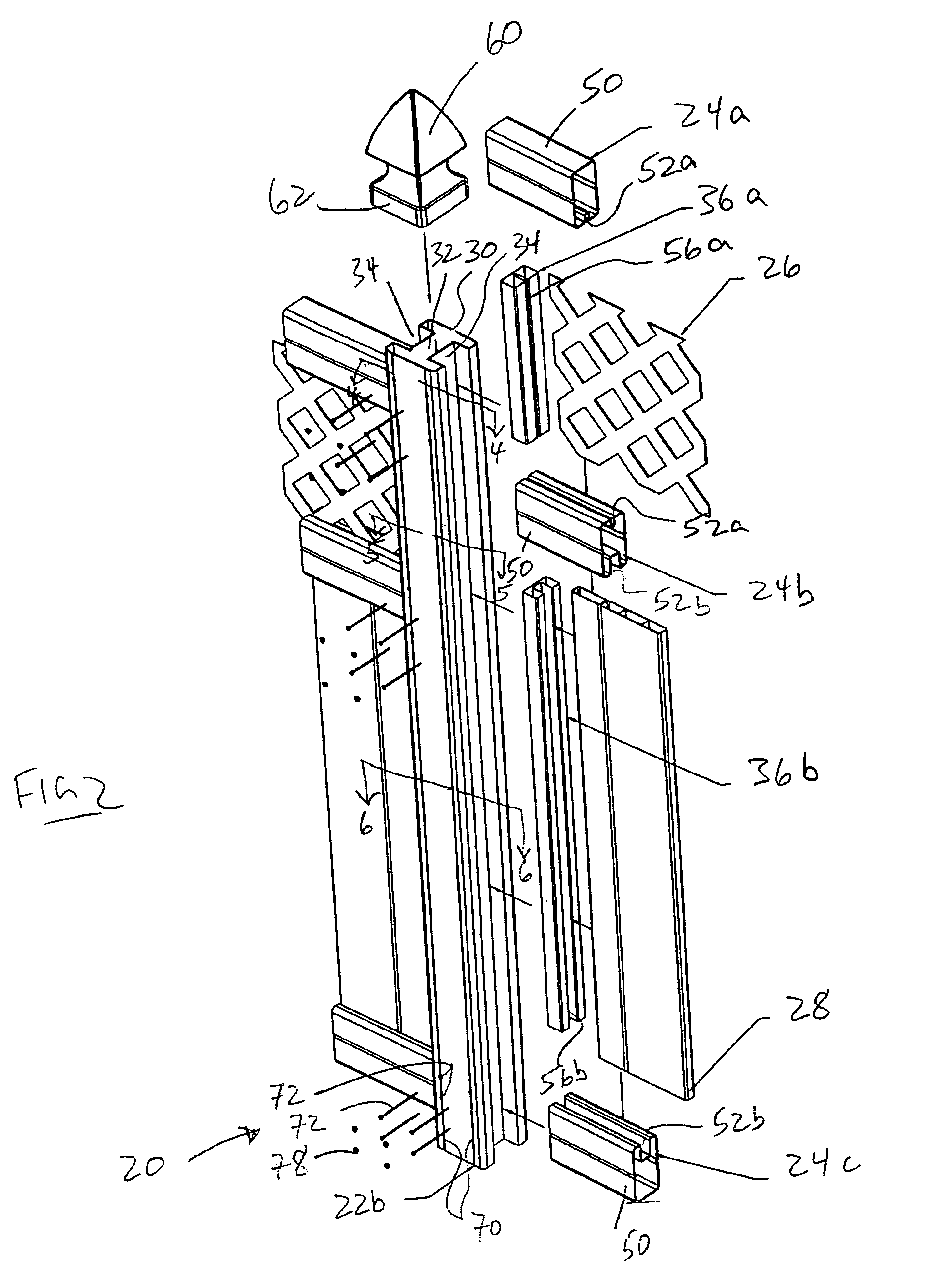
[0027] A modular fencing system in accordance with the present invention is shown generally at 20 in the Figures. The system includes a plurality of elongate posts 22 adapted for laterally supporting a plurality of elongate rails 24. Additional modular fencing components such as screens 26 and pickets 28 are similarly supported between rails 24 and posts 22.

[0028] Posts 22, as depicted in the figures, are generally square in cross section however, posts 22 may instead be round, polygonal, or any other suitable cross-sectional shape. The outer surface of posts 22 may be smooth as shown in the figures, or may be textured such as with a wood grain texture or any other desirable texture that can be formed thereon. As shown, the posts 22 are adapted to be secured in the ground within holes (not shown) that are filled with dirt or cement. Alternatively, the posts 22 may include a base (not shown) that may form a free-standing support or that may be secured with fasteners to a floor, a wa...


PUM


Abstract

The invention is directed to a fence post and a modular fencing system and method that utilizes same. The fence post has an elongated body having an outer wall and at least one elongated channel defined by said outer wall. The elongated channel has opposing sides and an open front. A fastener guide is defined in the outer wall along a plane that is generally orthogonal to the opposing sides of the component channel. In a further embodiment the component channel includes a lip protruding inwardly from the opposing sides adjacent to the front portion. In a further embodiment the fencing system includes post reinforcement members and rail reinforcement members. In other embodiments a fencing system is provided which includes posts, rails, pickets, screens and spacers that interconnect with the aid of fasteners to define a fence structure.

Description

FIELD OF THE INVENTION [0001] The present invention is directed to fencing systems and in particular to modular fencing systems. BACKGROUND OF THE INVENTION [0002] Modular fencing systems are becoming increasingly popular particularly those having components formed of extruded or molded materials such as polyvinylchloride (PVC) or other plastics or composites. Such materials are durable and resistant to rotting or insects. One problem with current modular fencing systems is the manner in which the fencing components are interconnected. Current systems are not adapted for securely fastening the components together in a simple, accurate and aesthetically pleasing way. [0003] There is a need to improve upon existing fencing system designs in order to simplify their assembly, to allow a variety of design variations from the same set of components, and improve their overall strength. Furthermore, there is a need to improve the manner of securing components together while maintaining a pl...

Claims


Application Information

Patent Timeline
IPC IPC(8): E04H17/16
CPCE04H17/168
Inventor COLANTONIO, SERGIOKOUTSOKOSTAS, GEORGETONON, MAURO
Owner ROYAL GROUP
Why Eureka
Try Eureka