Circularly polarized array antenna

Inactive Publication Date: 2006-06-22
TATUNG UNIVERSITY +1
View PDF2 Cites 67 Cited by
  • Summary
  • Abstract
  • Description
  • Claims
  • Application Information

AI Technical Summary

Benefits of technology

[0011] It also has the characteristics of low-cost and easy production to avoid the disadvantage of traditional ci

Problems solved by technology

Moreover, the production process for traditional circular

Method used


Image

  • Circularly polarized array antenna
  • Circularly polarized array antenna
  • Circularly polarized array antenna

Examples


Example

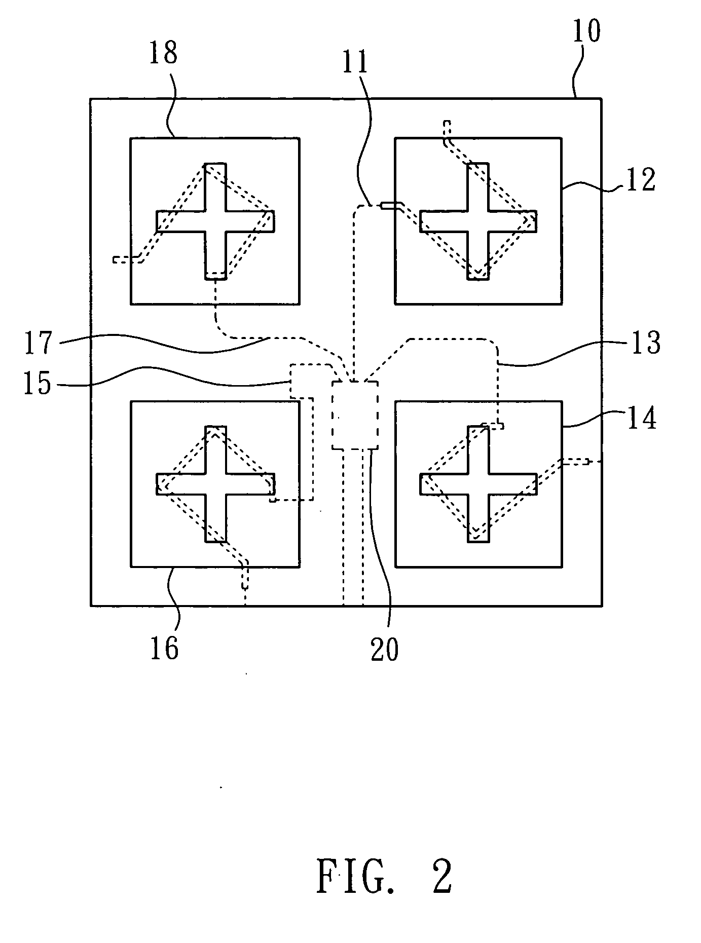
[0022] As shown in FIG. 2, the circularly polarized antenna 10 according to the present invention comprises the following elements:

[0023] antenna elements 12, 14, 16, and 18, with the structure of every antenna element being identical; the antenna 12 is used for illustration, the scope of claims shall, however, not be restricted.

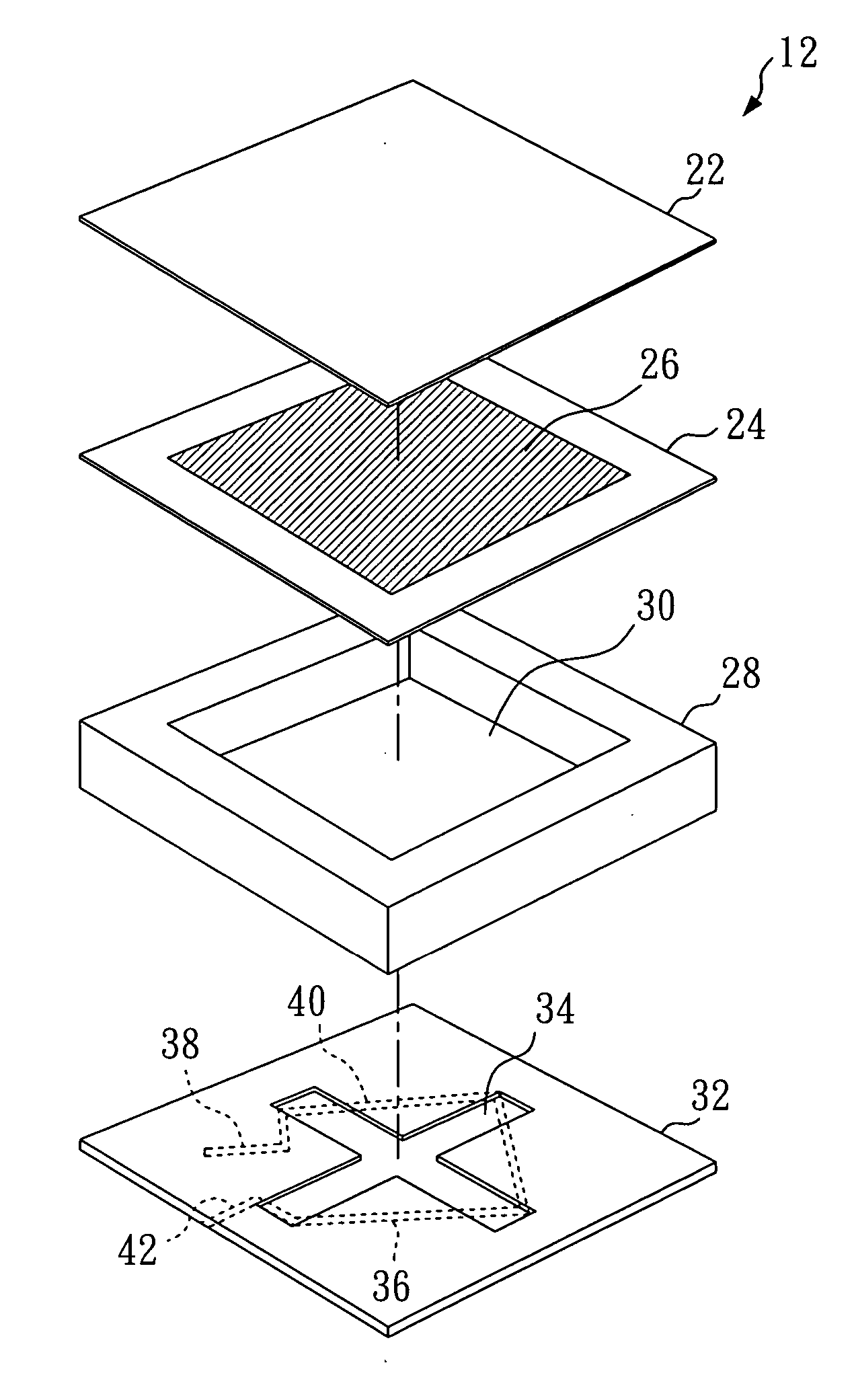
[0024] As shown in FIG. 3, the antenna element 12 further comprises: protection film 22, microstrip antenna (comprises supporting stratum 24 and patch 26 on the upper surface of the supporting stratum 24), substrate 28 with a cuboid-slot 30 in the center, and substrate 32 with cross-slot 34 on the upper surface and metal wire 36 on the lower surface. Substrate 32, with cross-slot 34 on the upper surface and metal wire 36 on the lower surface, can also serve as a slot antenna and combine with substrate 28 with the cuboid-slot 30 in the center to form the slot coupling apparatus. Therefore, the above-mentioned elements are arranged from the top down as prote...


PUM


Abstract

The invention relates to a circularly polarized array antenna for receiving and transmitting a circularly polarized signal. The circularly polarized array antenna comprises: a plurality of circularly polarized antennas with phase shift mechanism for receiving circularly polarized signals and transmitting the circularly polarized signals; a plurality of power lines which differ from each other in length and are coupled to the circularly polarized antennas respectively; and a power divider coupled to the power lines for receiving the circularly polarized signals. Wherein each of the circularly polarized antennas comprises a plurality of antenna elements and each comprises a microstrip antenna and a slot coupling apparatus.

Description

BACKGROUND OF THE INVENTION [0001] 1. Field of the Invention [0002] The present invention relates to a circularly polarized array antenna and, more particularly, to the circularly polarized array antenna that comprises a plurality of circularly polarized antennas. [0003] 2. Description of Related Art [0004] In the field of high-frequency communication (e.g., artificial satellite communication), due to the effect of signals passing through the ionosphere, the circularly polarized array antenna is generally used as a medium to receive circularly polarized signals. Moreover, due to the possibility for existence of two orthogonal polarization signals, every single polarized signal can be used to carry data so that orthogonal polarized signals (such as right hand or left hand signals) can be used in a neighboring area. [0005] As shown in FIG. 1, U.S. Pat. No. 4,543,579 entitled “Circular Polarization Antenna” discloses a traditional circular polarization antenna array antenna, comprising...

Claims


Application Information

Patent Timeline
IPC IPC(8): H01Q1/38H01Q9/04H01Q21/00H01Q21/06H01Q21/24
CPCH01Q9/0428H01Q9/0457H01Q21/0075H01Q21/065
Inventor CHANG, THE-NANLU, KO-HAN
Owner TATUNG UNIVERSITY
Why Eureka
Try Eureka