Fluid sensing device

Inactive Publication Date: 2019-08-01
GUANGZHOU SEAGULL KITCHEN & BATH PROD
View PDF3 Cites 0 Cited by
  • Summary
  • Abstract
  • Description
  • Claims
  • Application Information

AI Technical Summary

Benefits of technology

[0025]1. Fewer parts and easy production.
[0026]2. The magne

Problems solved by technology

Such technique has the following drawbacks: the material of the impeller blades with magnetism is special and expensive, and magnetic materials are involved in passing water and many related certifications are difficult to obtain.
Generally, whe

Method used


Image

  • Fluid sensing device
  • Fluid sensing device
  • Fluid sensing device

Examples


Example

[0040]The present invention will now be described in further detail with reference to the accompanying drawings in order to enable person skilled in the art to practice with reference to the description.

[0041]It should be noted that in the description of the present invention, the terms of “transverse”, “longitudinal”, “up”, “down”, “front”, “back”, “left”, “right”, “vertical”, “horizontal”, “top”, “bottom”, “inner”, “outer” and the like are based on the orientation or positional relationship shown in the drawings for convenience of describing the present invention and simplifying description. It is not intended or implied that the device or element must have a particular orientation and be constructed and operated in a particular orientation, and therefore it should not be construed as limiting the present invention.

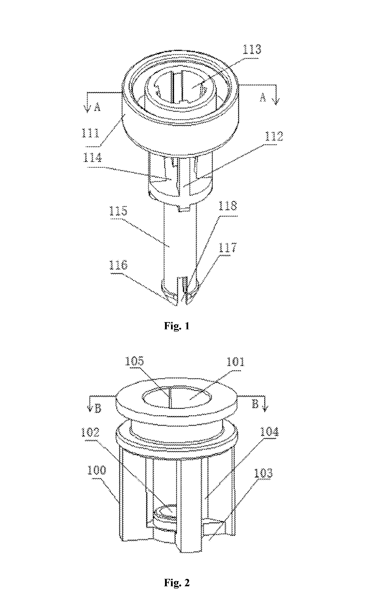
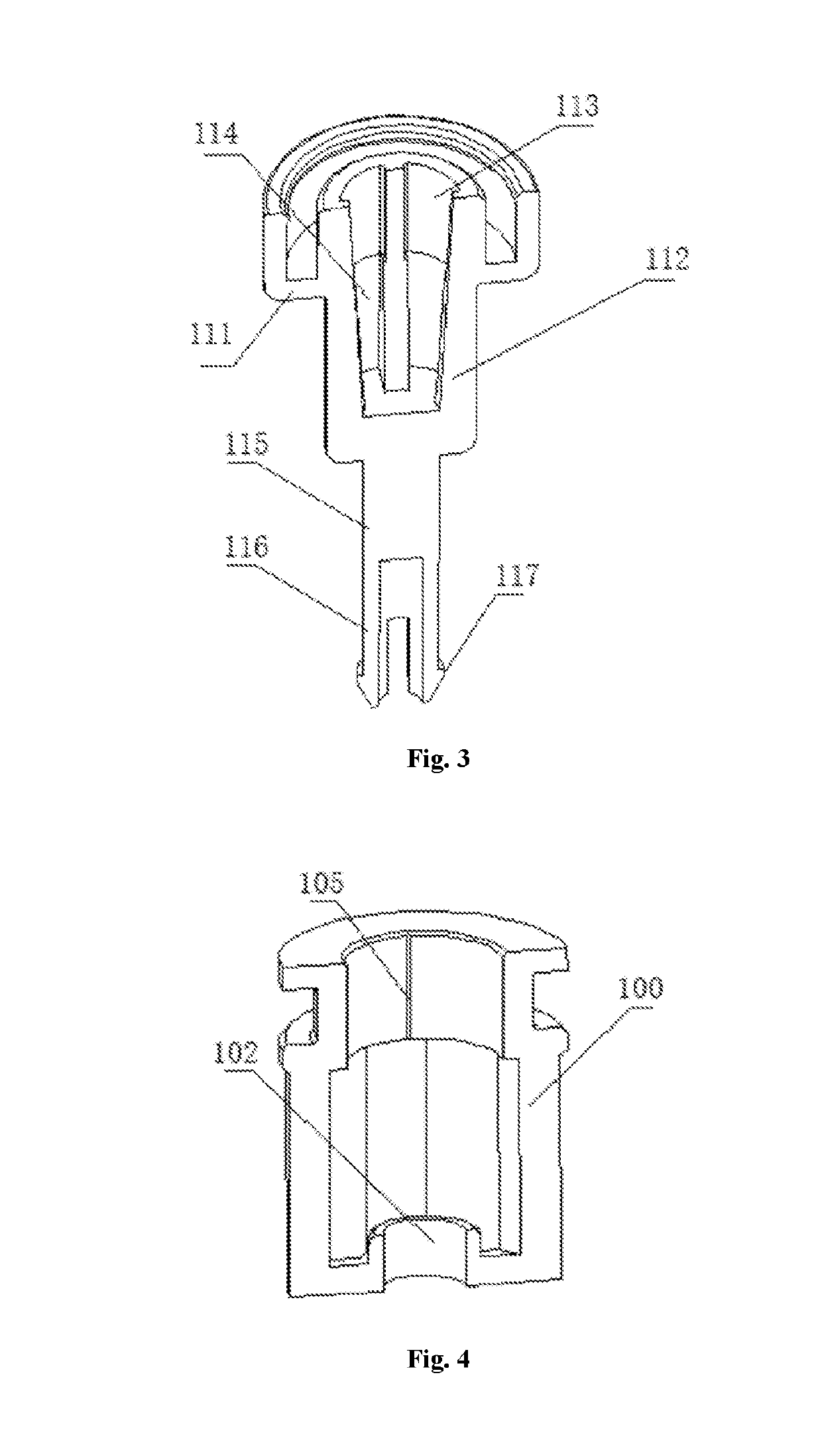
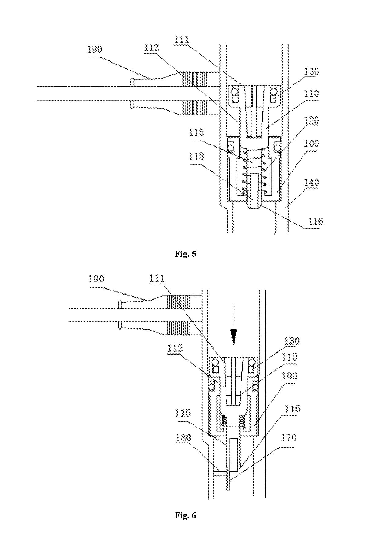
[0042]As shown in FIG. 1 to FIG. 10, the present invention provides a fluid sensing device provided in a flow path through which fluid flows, comprising: a base 100 fix...


PUM


Abstract

The invention discloses a fluid sensing device provided in a flow path through which fluid flows, including a base fixed in the flow path; a piston core rod disposed in the base and connected to the base through an elastic member, the piston core rod being provided with a pushing surface pushed by the fluid in the flow path; a magnet provided on the piston core rod; a magnetic sensing device provided on a side surface of the piston core rod to sense change of magnetic line received as change of position of the magnet, thereby determining whether fluid flows in flow path; wherein the elastic member is disposed such that direction of the restoring force thereof is opposite to the direction of fluid flow in flow path. The present invention has fewer parts and easy production, and can reduce judgement difference caused by low flow rate.

Description

CROSS-REFERENCE TO RELATED APPLICATION[0001]This application claims the priority benefit of China application serial no. 201810095349.6, filed on Jan. 31, 2018, and China application serial no. 201820163762.7, filed on Jan. 31, 2018. The entirety of each of the above-mentioned patent applications is hereby incorporated by reference herein and made a part of specification.BACKGROUNDTechnical Field of the Present Invention[0002]The present invention relates to a sensing device, in particular to a fluid sensing device.Technical Background of the Present Invention[0003]At present, commonly used fluid sensing devices generally have impeller blades. When fluid passes, the fluid flows through curved blades of the impeller blades, and the fluid exerts a force on the impeller blades to rotate the impeller blades. Some impeller blades itself have magnetism, one end of some impeller blades is connected to a magnetic block. When the impeller blades rotate, generated magnetic field is also chang...

Claims


Application Information

Patent Timeline
IPC IPC(8): G01F1/24
CPCG01F1/24G01P13/0013
Inventor GAO, SHUQIPENG, QIANFENGWEI, RONGBAOLUO, FU
Owner GUANGZHOU SEAGULL KITCHEN & BATH PROD
Why Eureka
Try Eureka