Telecommunications patching system that utilizes RFID tags to detect and identify patch cord interconnections

a patching system and patch cord technology, applied in the field of telecommunications systems, can solve the problems of inability to provide an employee, inability to update the log, and inability to provide a technician, and achieve the effect of facilitating rapid and accurate patch cord tracing

Active Publication Date: 2006-07-06
COMMSCOPE INC
View PDF11 Cites 221 Cited by
  • Summary
  • Abstract
  • Description
  • Claims
  • Application Information

AI Technical Summary

Benefits of technology

[0011] In view of the above discussion, a telecommunications patching system that facilitates rapid and accurate patch cord tracing are provided. According to an embodiment of the present invention, a patch panel having a plurality of connector ports includes an RFID reader and a plurality of RF antennas. Each RF antenna is associated with one or more patch panel connector ports. A plurality of patch cords are configured to selectively interconnect pairs of the connector ports. Each patch cord has opposite ends and a respective connector secured to each end that is configured to be removably secured within a connector port. Each connector of a respective patch cord also includes an RFID tag. The RFID tags for a respective patch cord have the same unique identifier stored therewithin. The RF antenna associated with a patch panel connector port emits RF signals that are configured to cause a patch cord connector RFID tag to transmit its identifier. Each RF antenna detects the transmitted identifier of a patch cord connector RFID tag when the respective patch cord connector is inserted within, and removed from, a connector port associated with a respective RF antenna. The detected RFID tag identifier is then transmitted to the RFID reader and stored within a database that logs patch cord connectivity.

Problems solved by technology

When an employee changes office locations, it may not be desirable to provide that employee with new exchange numbers.
However, technicians may neglect to update the log each and every time a change is made.
Inevitably, the log is less than 100% accurate and a technician has no way of reading where each of the patch cords begins and ends.
It may take a significant amount of time for a technician to manually trace a particular patch cord, particularly within a collection of other patch cords.
Furthermore, manual tracing may not be completely accurate and technicians may accidentally go from one patch cord to another during a manual trace.
Such errors may result in misconnected telecommunication lines which must be later identified and corrected.
Also, it may be difficult to identify the correct port to which a particular patch cord end should be connected or disconnected.
Thus, ensuring that the proper connections are made can be very time-consuming, and the process is prone to errors in both the making of connections and in keeping records of the connections.

Method used


Image

  • Telecommunications patching system that utilizes RFID tags to detect and identify patch cord interconnections
  • Telecommunications patching system that utilizes RFID tags to detect and identify patch cord interconnections
  • Telecommunications patching system that utilizes RFID tags to detect and identify patch cord interconnections

Examples


Embodiment Construction

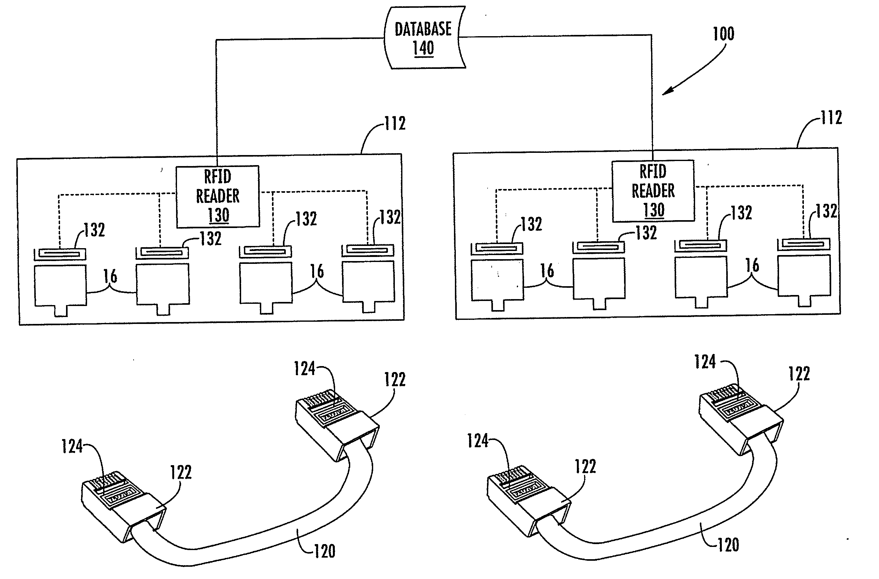
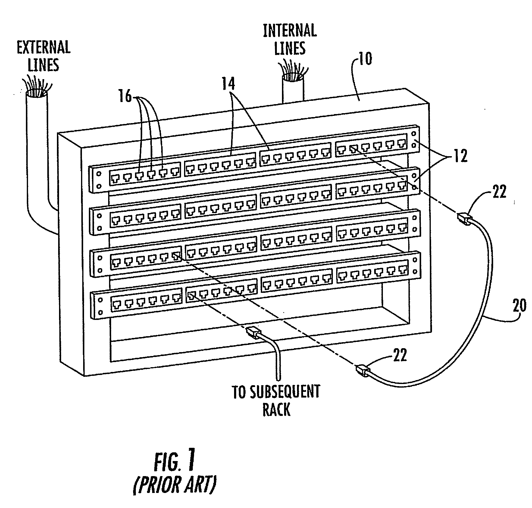
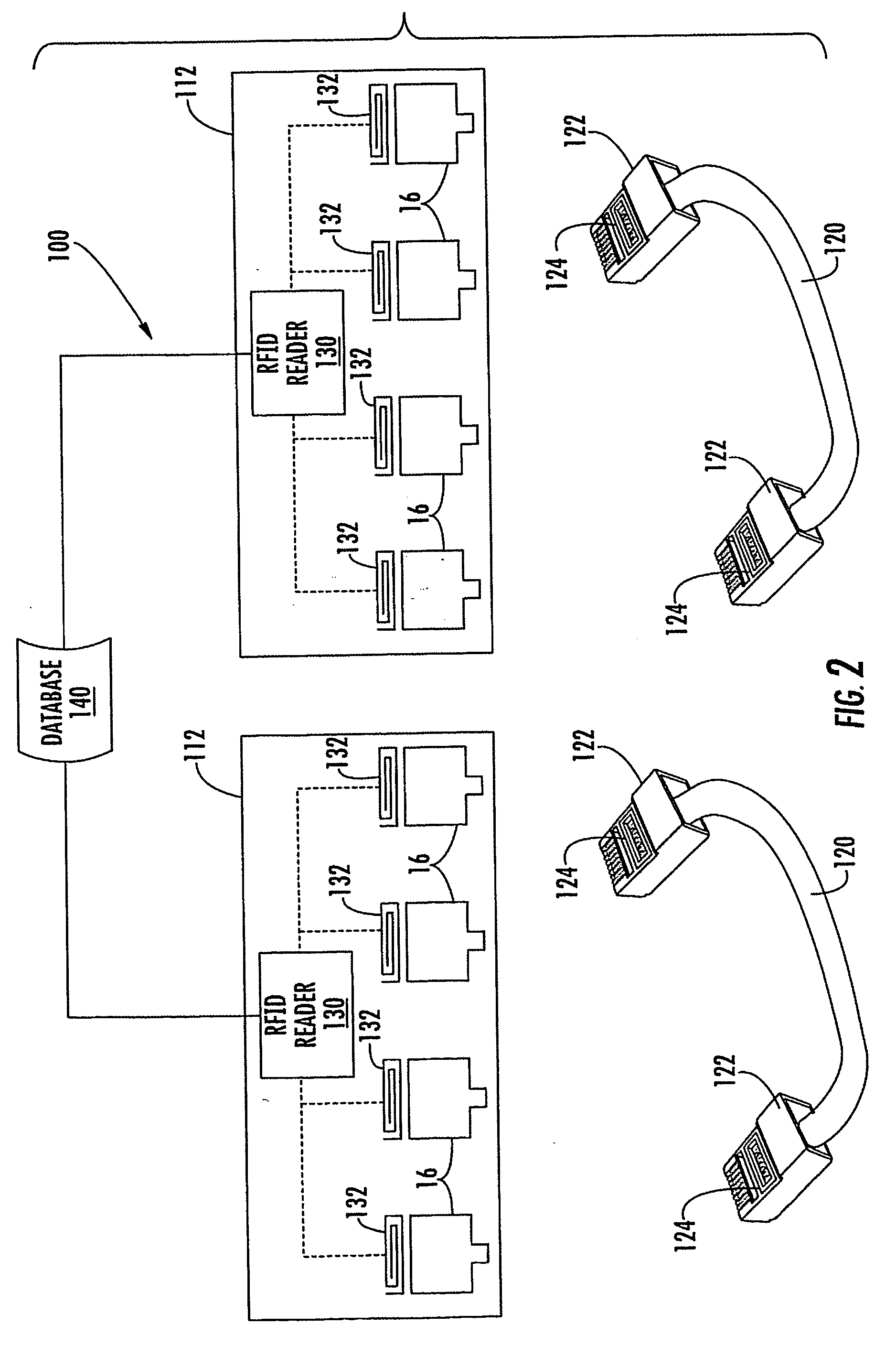
[0020] The present invention now is described more fully hereinafter with reference to the accompanying drawings, in which embodiments of the invention are shown. This invention may, however, be embodied in many different forms and should not be construed as limited to the embodiments set forth herein; rather, these embodiments are provided so that this disclosure will be thorough and complete, and will fully convey the scope of the invention to those skilled in the art.

[0021] Unless otherwise defined, all technical and scientific terms used herein have the same meaning as commonly understood by one of ordinary skill in the art to which this invention belongs. The terminology used in the description of the invention herein is for the purpose of describing particular embodiments only and is not intended to be limiting of the invention. As used in the description of the invention and the appended claims, the singular forms “a”, “an” and “the” are intended to include the plural forms ...


PUM


Abstract

A telecommunications patching system includes a patch panel having a plurality of connector ports, and having an RFID reader and RF antennas associated with the connector ports. A plurality of patch cords are configured to selectively interconnect pairs of the connector ports. Each patch cord has opposite ends and a respective connector secured to each end that is configured to be removably secured within a connector port. Each connector of a respective patch cord includes an RFID tag. The RFID tags for a respective patch cord have the same unique identifier stored therewithin. The RF antenna associated with a connector port emits RF signals that cause a patch cord connector RFID tag to transmit its identifier. Each RF antenna detects the transmitted identifier of a patch cord connector RFID tag when the respective patch cord connector is inserted within, and removed from, a respective one of the connector ports.

Description

RELATED APPLICATION [0001] This application claims the benefit of and priority to U.S. Provisional Patent Application No. 60 / 608,962 filed Dec. 6, 2004, the disclosure of which is incorporated herein by reference as if set forth in its entirety.FIELD OF THE INVENTION [0002] The present invention relates generally to telecommunications systems and, more particularly, to telecommunications patching systems. BACKGROUND OF THE INVENTION [0003] Many businesses have dedicated telecommunication systems that enable computers, telephones, facsimile machines and the like to communicate with each other, through a private network, and with remote locations via a telecommunications service provider. In most buildings, the dedicated telecommunications system is hard wired using telecommunication cables that contain conductive wire. In such hard wired systems, dedicated wires are coupled to individual service ports throughout the building. The wires from the dedicated service ports extend through ...

Claims


Application Information

Patent Timeline
Patent Type & Authority Applications(United States)
IPC IPC(8): H01R29/00
CPCH01R13/465H04Q1/138H01R29/00H01R13/518
Inventor GERMAN, MICHAEL G.CHOUDHURY, GOLAM MABUDMACAULEY, DANIEL WARRENSATTERTHWAITE, DANNY L.TUCKER, PETER T.
Owner COMMSCOPE INC
Why Eureka
Try Eureka