
Electronic payment terminal with active cover

a technology of electronic payment terminal and active cover, which is applied in the field of secure electronic payment terminal, can solve the problems of cumbersome use of electronic payment terminal and separate electronic signature device, easy scratching of electronic screen and/or rapid wear, and time-consuming and expensive recertification procedure of electronic payment terminal

Inactive Publication Date: 2006-07-20
ZANK ANTHONY E +1
View PDF26 Cites 64 Cited by
  • Summary
  • Abstract
  • Description
  • Claims
  • Application Information

AI Technical Summary

Benefits of technology

[0011] Moreover, for terminals adapted to enter informational data, it is desirable to shield the keypad from observation by third parties, so that the individual's information is not compromised and is kept secret.

Problems solved by technology

The erasure of such proprietary internal information requires that the electronic payment terminal go through a time consuming and expensive recertification procedure.
A problem with electronic signature devices is that the electronic screen is easily scratched and / or quickly wears out.
Banking and retail establishments often find it cumbersome to use both an electronic payment terminal and a separate electronic signature device, because the use of the two separate devices frequently takes up an undue amount of precious counter space.
However, such attempts have been less than wholly successful.
One problem with combining electronic signature and electronic payment terminals is that the electronic signature screen tends to be at an awkward angle with respect to the signator.
This often leads to signatures which do not closely match the ink-on-paper signature of the signator, so that the electronic signature is rejected as false.
Another problem with combined electronic signature and electronic payment terminal units is that the face of such units is unduly large and, again, takes up an undue amount of counter space.
Finally, a problem with combined electronic signature and electronic payment terminal units is that, when the signature screen of the electronic signature device has to be replaced, the internals of the housing, which include the electronic payment terminal, must be breached.
Under the new industry group protocols, such breaching of the electronic payment terminal housing will require the electronic payment terminal portion to go through an expensive and time-consuming recertification process.

Method used


Image

  • Electronic payment terminal with active cover
  • Electronic payment terminal with active cover
  • Electronic payment terminal with active cover

Examples


Embodiment Construction

[0025] The following discussion describes in detail one embodiment of the invention and several variations of that embodiment. This discussion should not be construed, however, as limiting the invention to those particular embodiments. Practitioners skilled in the art will recognize numerous other embodiments as well.

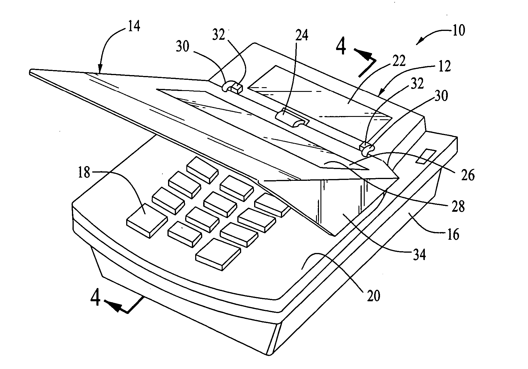
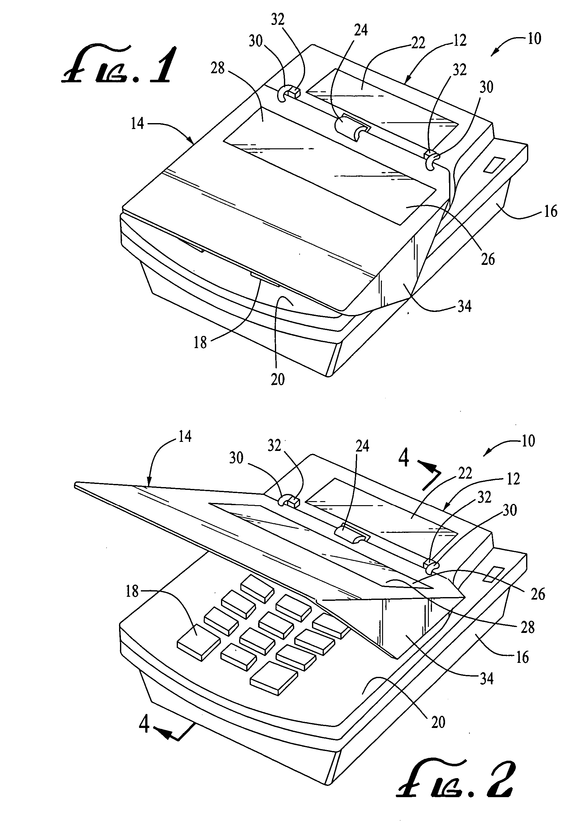
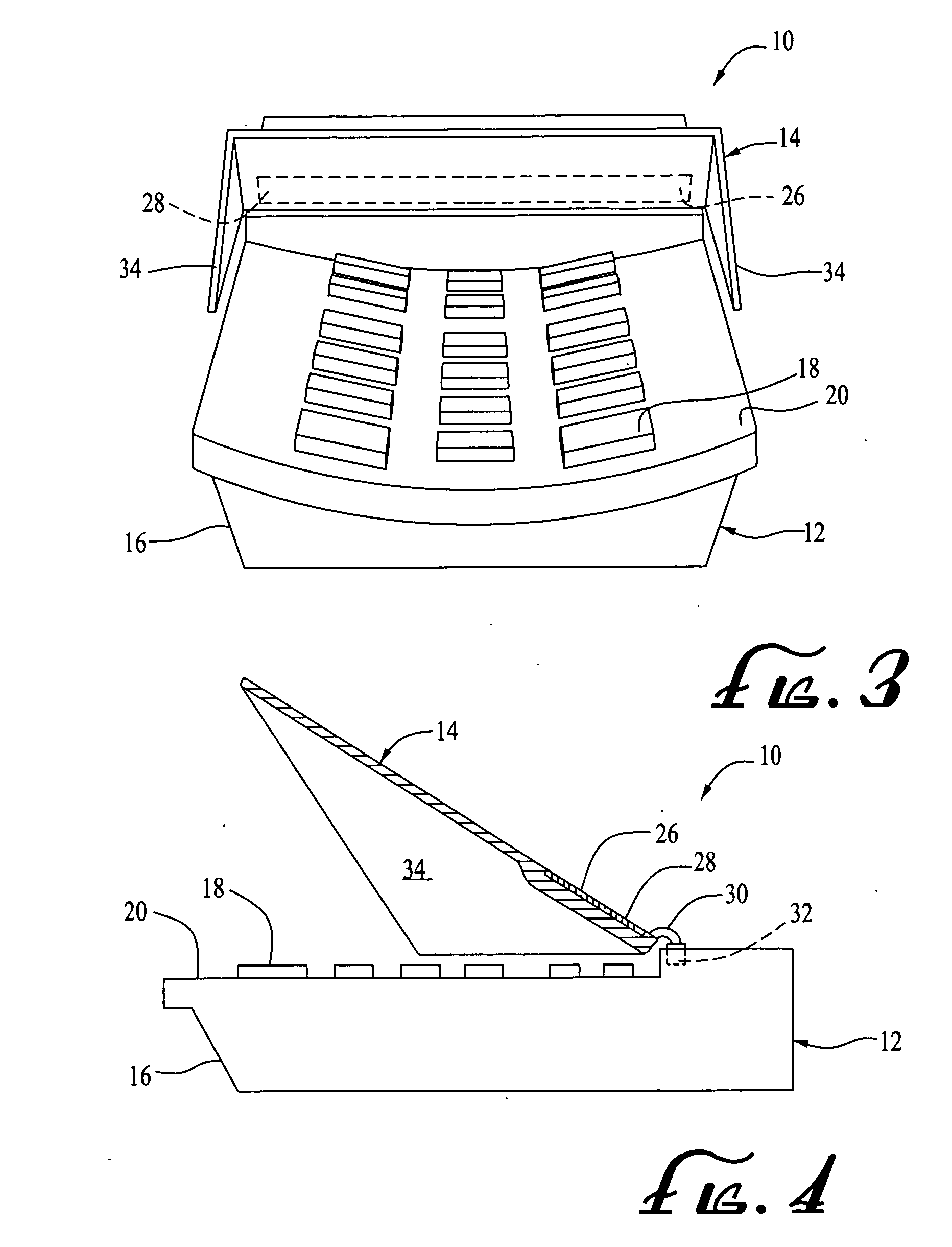
[0026] The invention is an apparatus 10 for facilitating commercial transaction payments. The apparatus comprises a secured electronic payment terminal 12 and a unique keyboard cover 14.

[0027] The secured electronic payment terminal 12 can be any one of the wide variety of secured electronic payment terminal designs. The secured electronic payment terminal 12 comprises a housing 16, an external keyboard 18 protruding above the housing 16 and internal electronic circuitry (not shown) for gathering information provided by the operation of the keyboard 18 and for exchanging information with external, remotely located computers.

[0028] A typical secured electronic payment...


PUM


Abstract

An apparatus useful in facilitating commercial transaction payments as a secured electronic payment terminal and a thin keyboard cover. The keyboard cover is adjustably attached to the electronic payment terminal so that the keyboard cover can alternatively serve to cover the keyboard or to swing away from the keyboard to provide a security panel. The keyboard cover is “active,” in that it incorporates a data communicator for transmitting or receiving data from an outside source. In one embodiment, the data communicator includes a signature pad. The keyboard cover is removable from the electronic payment terminal for maintenance and / or replacement without having to access the internals of the electronic payment terminal, including its electronic circuitry.

Description

FIELD OF THE INVENTION [0001] This invention relates generally to secured electronic payment terminals and similar equipment. BACKGROUND OF THE INVENTION [0002] Electronic payment terminals have become very common as tools in most banking and retail transactions. Many such electronic payment terminals require a keypad so that the payor can enter his or her “PIN” number. [0003] Security for such electronic payment terminals is extremely important. Recently, several trade associations, including EMVCo, LLC, have proposed protocols for electronic payment terminals which incorporate stringent security procedures. One such security procedure requires that each electronic payment terminal go through a rigorous certification procedure to certify the security features built into the electronic payment terminal. Additionally, such security procedures typically require that all secure information within the electronic payment terminal be automatically erased upon any breaching of the electron...

Claims


Application Information

Patent Timeline
Patent Type & Authority Applications(United States)
IPC IPC(8): G09G5/00
CPCG07F7/10G07G1/0018
Inventor ZANK, ANTHONY E.ZANK, PAUL M.
Owner ZANK ANTHONY E
Learn More