Signal-quality evaluation device, signal adjustment method, optical-signal evaluation system, and optical transmission system

Inactive Publication Date: 2006-07-20
SUMITOMO ELECTRIC IND LTD
View PDF52 Cites 7 Cited by
  • Summary
  • Abstract
  • Description
  • Claims
  • Application Information

AI Technical Summary

Benefits of technology

[0009] It is an object of the present invention to provide a signal-quality evaluation device and a signal adjustment method in which the time required for evaluating the quality of optical signals can be shortened and which are superior in applic

Problems solved by technology

However, determining a BER requires a long period of time for measurement, and especially if the BER is small, the time required for measurement is even longer.
In this method, however, since the optical signal must be processed at a transmitting side, it is difficult to apply this method to an optical network that has a plurality of transmitting sides and a plurality of receiving sides.
Moreover, subjecting an optical signal to

Method used


Image

  • Signal-quality evaluation device, signal adjustment method, optical-signal evaluation system, and optical transmission system
  • Signal-quality evaluation device, signal adjustment method, optical-signal evaluation system, and optical transmission system
  • Signal-quality evaluation device, signal adjustment method, optical-signal evaluation system, and optical transmission system

Examples


Example

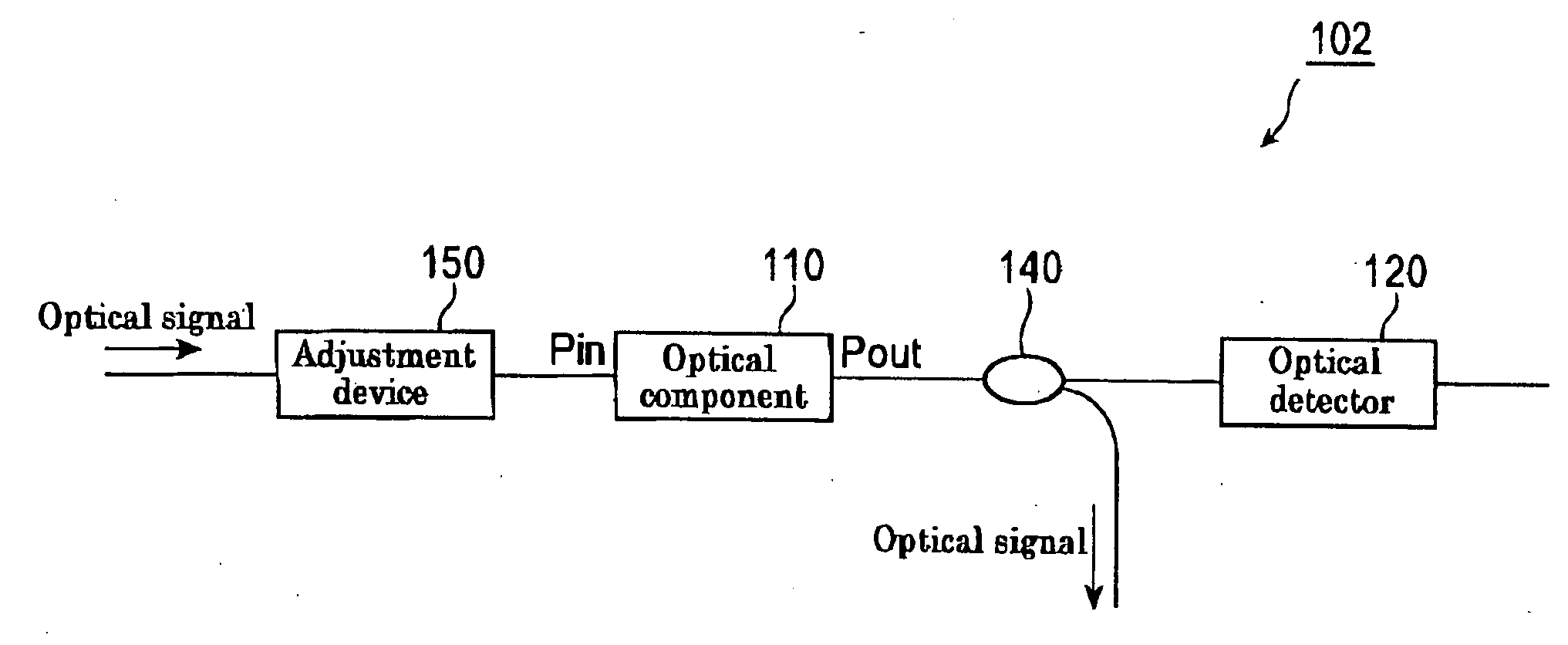
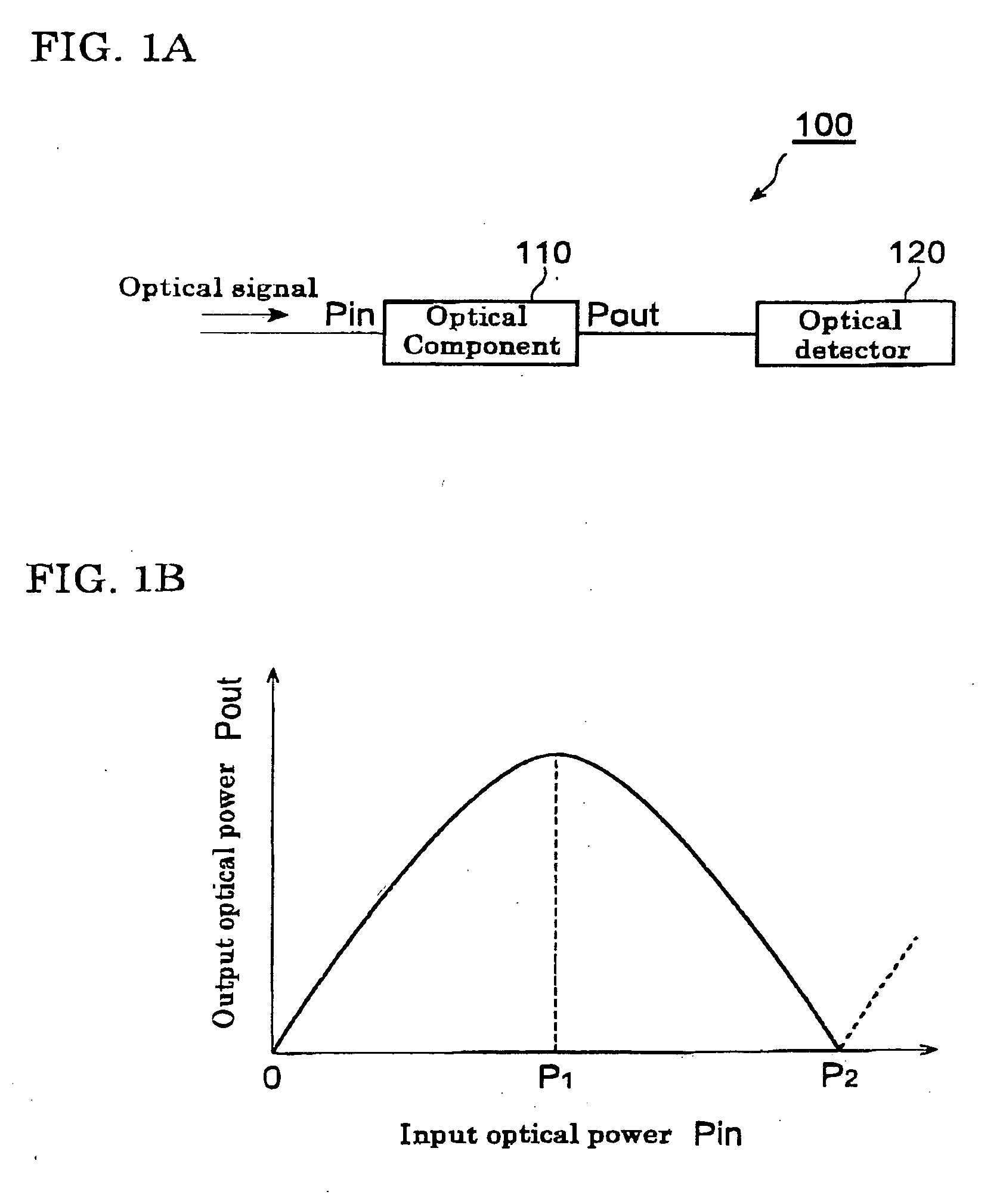
[0039] A principle of optical-signal evaluation in a signal-quality evaluation device and a signal adjustment method according to embodiments of the present invention will be described first. FIG. 1A is a block diagram of a signal-quality evaluation device 100 according to an embodiment of the present invention. FIG. 1B is a graph illustrating input-output characteristics of an optical component 110 included in the signal-quality evaluation device 100.

[0040] The signal-quality evaluation device 100 has an optical output detector 120 and the optical component 110 functioning as a converter. The optical component 110 outputs input light by reflecting or transmitting it, and as shown in FIG. 1B, an output optical power Pout is a function of an input optical power Pin, the function Pout(Pin) having at least one maximum point. The function Pout(Pin) may have a plurality of maximum points. The optical output detector 120 detects the time-average power of the light output from the optical...


PUM


Abstract

Provided are a signal-quality evaluation device and a signal adjustment method which require shorter evaluation time and which have high flexibility of application. A signal quality evaluation device 100 includes an optical component 110 and an optical output detector 120. In the optical component 110, an output optical power Pout is a function of an input optical power Pin, and this function Pout(Pin) has at least one maximum point. The optical output detector 120 detects the time-average power of light output from the optical component 110.

Description

BACKGROUND OF THE INVENTION [0001] 1. Field of the Invention [0002] The present invention relates to a signal-quality evaluation device for evaluating the quality of optical signals, a signal adjustment method, and an optical-signal evaluation system and an optical transmission system which are equipped with such signal-quality evaluation device. [0003] 2. Description of the Related Art [0004] In a future optical transmission system, an optimal condition for transmitting optical signals will tend to change according to the system structure that becomes more complicated due to an increase in transmission capacity. Therefore, adjustment means (e.g. dispersion compensation means) for constantly optimizing the transmission condition is necessary. Furthermore, in order to utilize such adjustment means effectively, a device that evaluates and monitors the quality of an optical signal is also necessary. [0005] In order to evaluate the quality of an optical signal, a certain parameter must ...

Claims


Application Information

Patent Timeline
IPC IPC(8): H04B10/08H04B17/00
CPCH04B10/2507
Inventor TANAKA, MASATO
Owner SUMITOMO ELECTRIC IND LTD
Why Eureka
Try Eureka