Light emitting device with a micro-reflection structure carrier

Inactive Publication Date: 2006-12-26
EPISTAR CORP
View PDF32 Cites 33 Cited by
  • Summary
  • Abstract
  • Description
  • Claims
  • Application Information

AI Technical Summary

Benefits of technology

[0009]It is an advantage of the present invention that the time for the growth of the epitaxial layer is reduced and carrier is thick enough to form the specific geometric figures. Therefore the cost is lowered, and the light emitting efficiency is increased. Furthermore, since the light emitting device with the micro-reflection structure carrier disclosed in the claimed invention utilizes the transparent adhesive layer to adhere to the surface of the

Problems solved by technology

For developing light emitting devices, one of the most important issues is to raise light emitting efficiency of light emitting devices.
Since the light emitting device is connected to a small part of the carrier at the top of the micro-reflector and the connecting area is small, the mechanical strength

Method used


Image

  • Light emitting device with a micro-reflection structure carrier
  • Light emitting device with a micro-reflection structure carrier
  • Light emitting device with a micro-reflection structure carrier

Examples


Embodiment Construction

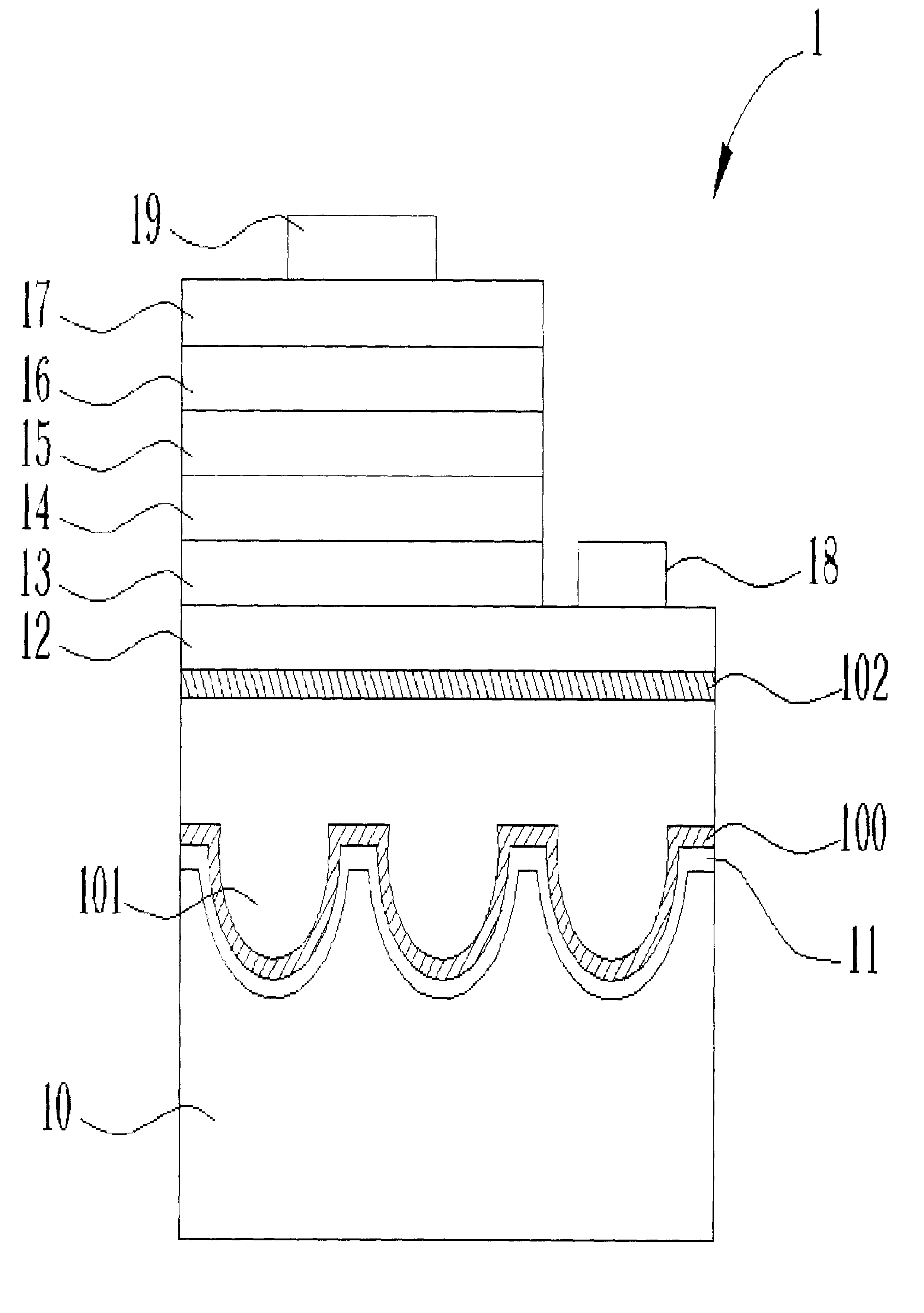
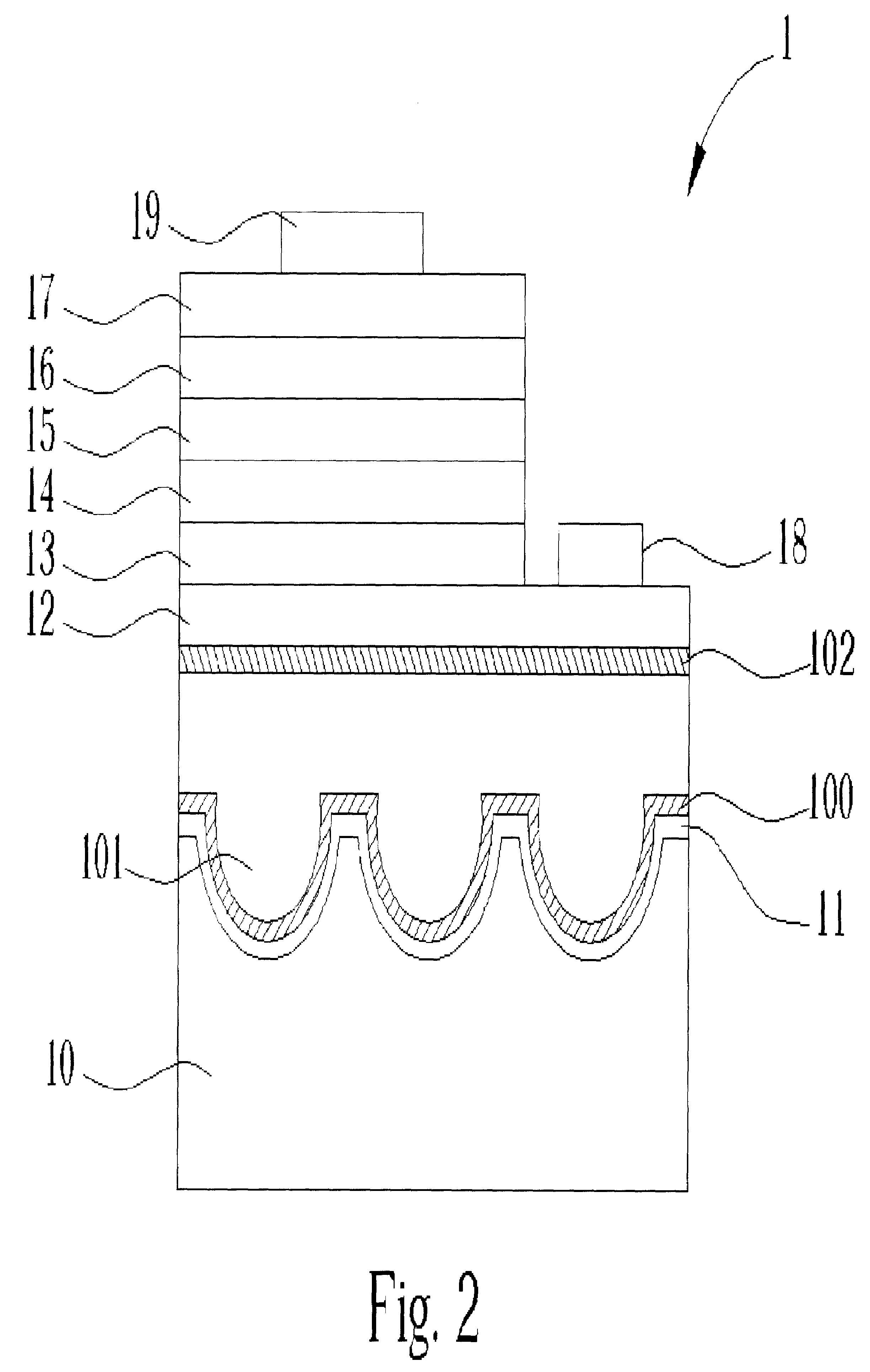
[0015]Please refer to FIG. 2: FIG. 2 is a first embodiment of the present invention light emitting device with a micro-reflection structure carrier. 1 is a light emitting device with a micro-reflection structure carrier according to the present invention. 1 comprises a micro-reflection structure carrier 10, a reflection layer 11 formed over the micro-reflection structure carrier 10, a first reaction layer 100 formed over the reflection layer 11, a transparent adhesive layer 101 formed over the first reaction layer 100, a second reaction layer 102 formed over the transparent adhesive layer 101, a transparent conductive layer 12 formed over the second reaction layer 102, wherein a first surface area and a second surface are comprised on an upper surface of the transparent conductive layer 12, a first contact layer 13 formed over the first surface area, a first cladding layer 14 formed over the first contact layer 13, a light emitting layer 15 formed over the first cladding layer 14, a...


PUM


Abstract

A light emitting device includes a micro-reflection structure carrier, which is formed by performing etching process on a carrier, a reflection layer, a light emitting layer, and a transparent adhesive layer, wherein the reflection layer is formed over the micro-reflection structure carrier and adheres to the light emitting layer through the transparent adhesive layer.

Description

BACKGROUND OF INVENTION[0001]1. Field of the Invention[0002]The present invention relates to a light emitting device, and more particularly, to a light emitting device with a micro-reflection structure carrier.[0003]2. Description of the Prior Art[0004]Light emitting devices are extensively applied to many fields. For instance, light emitting devices are utilized in optical displays, laser diodes, traffic lights, data storages, communication devices, illumination devices, and medical instruments. For developing light emitting devices, one of the most important issues is to raise light emitting efficiency of light emitting devices.[0005]In US publication No. US 2002 / 0017652 A1, an AlGaInP light emitting device of an embedded micro-reflection structure is disclosed. Please refer to FIG. 1. FIG. 1 is a prior art AlGaInP light emitting device of an embedded micro-reflection structure. LM is a metallic layer, CS is a conductive substrate, LE is an epitaxial layer with a micro-reflection ...

Claims


Application Information

Patent Timeline
IPC IPC(8): H01L29/06H01L33/00H01L27/15H01L31/00H01L33/60H01L33/62H01S5/10
CPCH01L33/46H01L2933/0091
Inventor HSIEH, MIN-HSUNLIU, WEN-HUANG
Owner EPISTAR CORP
Why Eureka
Try Eureka