Light emitting device

a light emitting device and light technology, applied in the direction of discharge tube luminescnet screens, discharge tube/lamp details, incadescent envelopes/vessels, etc., to achieve the effect of improving light emitting efficiency, different indices of refraction, and raising the possibility of light extraction of light emitting devices

Active Publication Date: 2006-07-27
EPISTAR CORP
View PDF3 Cites 41 Cited by
  • Summary
  • Abstract
  • Description
  • Claims
  • Application Information

AI Technical Summary

Benefits of technology

[0037] The present invention is to bond the transparent substrate and the light emitting stack having the diffusing surface together by the transparent adhesive layer. The light emitting stack and the transparent adhesive layer have different indices of refraction, such that the possibility of light extraction of the light emitting device is raised, and the light emitting efficiency is improved, too.

Problems solved by technology

How to improve the light emitting efficiency of light emitting devices is an important issue in this art.

Method used


Image

  • Light emitting device
  • Light emitting device
  • Light emitting device

Examples


Embodiment Construction

[0047] Reference will now be made in detail to the present preferred embodiments of the invention, examples of which are illustrated in the accompanying drawings. Wherever possible, the same reference numbers are used in the drawings and the description to refer to the same or like parts.

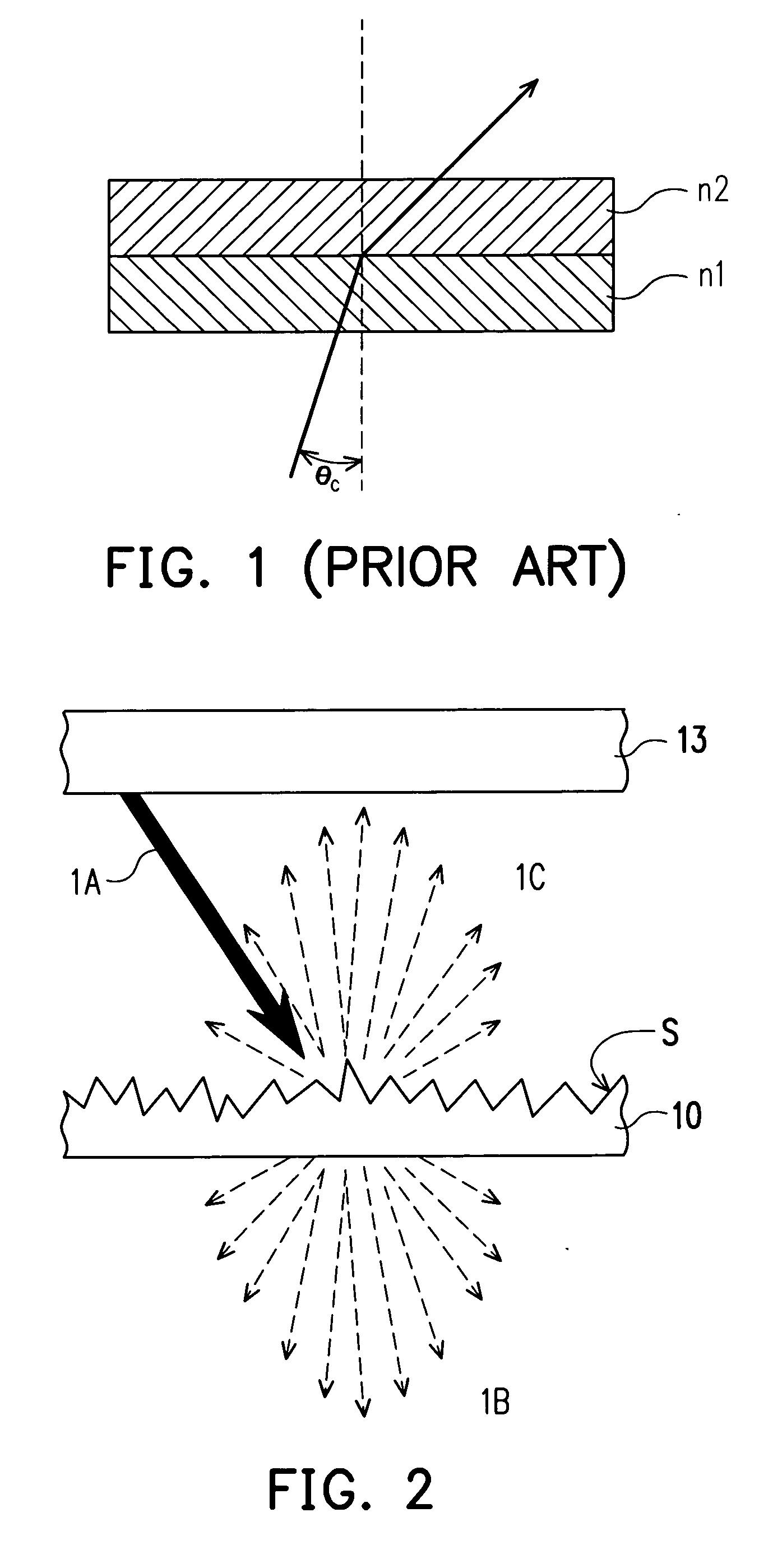
[0048]FIG. 2 is a schematic diagram showing a light field of the present invention. Referring to FIG. 2, when a light 1A generated from a light emitting layer 13 is directed towards a diffusing surface S, a portion of the light 1A is refracted to a transparent substrate 10 to form a light field 1B, and another portion of the light 1A is diffused by the diffusing surface S to form a light field 1C. The present invention utilizes the presence of the diffusing surface S to make the light, which is restricted to the critical angle, be reflected to the light emitting layer 13 after diffusion, and the light will be extracted from the front of the light emitting layer 13, such that the light extraction ef...


PUM


Abstract

A light emitting device having a transparent substrate, a light emitting stack, and a transparent adhesive layer is provided. The light emitting stack is disposed above the transparent substrate and comprises a diffusing surface. The transparent adhesive layer is disposed between the transparent substrate and the diffusing surface of the light emitting stack; an index of refraction of the light emitting stack is different from that of the transparent adhesive layer.

Description

CROSS-REFERENCE TO RELATED APPLICATION [0001] This application claims the priority benefit of Taiwan application serial no. 94102193, filed on Jan. 25, 2005. All disclosure of the Taiwan application is incorporated herein by reference. BACKGROUND OF THE INVENTION [0002] 1. Technical Field [0003] The present invention relates to a light emitting device and in particular to a light emitting device having a diffusing surface. [0004] 2. Description of the Related Art [0005] Light emitting devices have been employed in a wide variety of applications, including optical displays, traffic lights, data storage apparatus, communication devices, illumination apparatus, and medical treatment equipment. How to improve the light emitting efficiency of light emitting devices is an important issue in this art. [0006] Referring to FIG. 1, according to Snell's law, when a light is directed from one material with an index of refraction n1 towards another material with an index of refraction n2, the li...

Claims


Application Information

Patent Timeline
Patent Type & Authority Applications(United States)
IPC IPC(8): H01L33/00H01L33/10H01L33/22H01L33/30H01L33/42
CPCH01L33/22
Inventor HSIEH, MIN-HSUNHSU, TA-CHENGPENG, WEI-CHIHLEE, YA-JU
Owner EPISTAR CORP
Why Eureka
Try Eureka