
Three-dimensional display device

a display device and three-dimensional technology, applied in the field of three-dimensional (3d) image display devices, can solve the problems of reducing the aperture ratio of the display, lack of time-multiplexing concept, and inability to precisely control the light direction

Active Publication Date: 2013-08-20
DELTA ELECTRONICS INC
View PDF8 Cites 1 Cited by
  • Summary
  • Abstract
  • Description
  • Claims
  • Application Information

AI Technical Summary

Benefits of technology

The disclosure provides a method for making a light modulating device by creating a cavity between two substrates and filling it with different light modulating materials that change their refractive index when electrified. The device uses a special arrangement of electrodes and a partition wall to create separate modulation zones, which can be controlled separately. The technical effect is a more precise and versatile light modulating device with improved performance and efficiency.

Problems solved by technology

However, using a TFT driving mechanism may dramatically reduce the aperture ratio of the display.
Although the electrowetting display may deflect light beams, it lacks the concept of time-multiplexing.
In addition, the light direction may not be exactly controlled due to the fact that the contact angle of the liquids may mistake while a voltage is applied to the light redirecting element.
However, this design needs a specific circuit layout to individually control each electrode, and it may increase design complexity.
However, holography needs small pixels and huge memory / calculation speeds.
According to related arts, the light modulating element manufactured of the electrowetting concept has problems as below.
When the adhesive force between the liquids and the surface of the light modulating element is insufficient, the first and second liquids may be misplaced.
Furthermore, the first fluid surface is easily deformed when applied with a voltage, and the first and second fluids are easily misplaced due to insufficient adhesive forces between the liquids and the surface of the light modulating element.
Even if the applied voltage is stopped, the tension between the polar liquid and surrounding object is too small to make the polar fluid return back its original shape / position.

Method used


Image

  • Three-dimensional display device
  • Three-dimensional display device
  • Three-dimensional display device

Examples


Embodiment Construction

[0037]The following description is of the best-contemplated mode of carrying out the invention. This description is made for the purpose of illustrating the general principles of the invention and should not be taken in a limiting sense. The scope of the invention is best determined by reference to the appended claims.

[0038]A polar light modulating medium forms droplets having a high contact angle (>90°) on a hydrophobic material surface, and thus the hydrophobic material is a high-contact-angle material for the polar light modulating medium. Moreover, the non-polar light modulating medium form droplets having a low contact angle on the hydrophobic material surface and thus the hydrophobic material is a low-contact-angle material for the non-polar light modulating medium.

[0039]A polar light modulating medium forms droplets having a low contact angle (>90°) on a hydrophilic material surface, and thus the hydrophilic material is a low-contact-angle material for the polar light modulat...


PUM

PropertyMeasurementUnit
contact angleaaaaaaaaaa
refresh frequencyaaaaaaaaaa
timeaaaaaaaaaa

Abstract

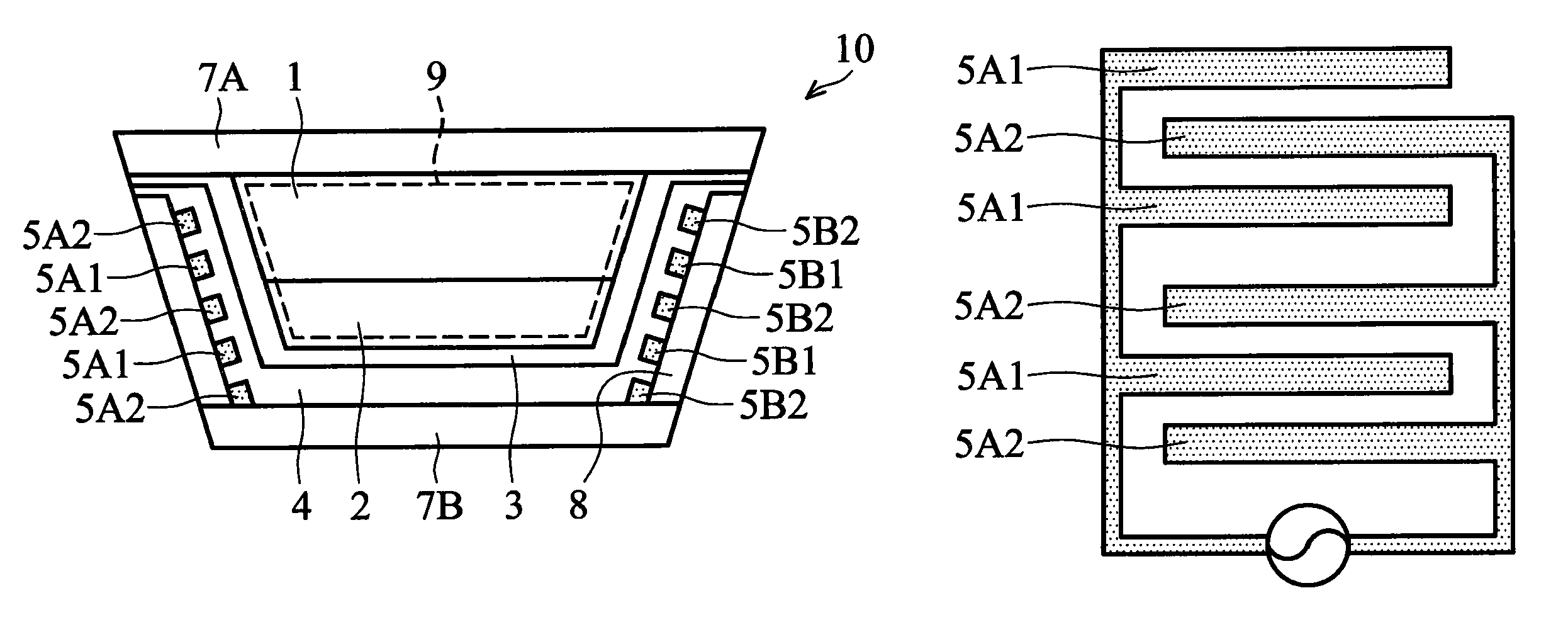
A 3D image display device with high resolution is disclosed. The device may deflect left and right eye images to a left and right eye of a viewer, respectively. As such, the viewer may see 3D images. The 3D image display device includes a plurality of electrically switchable light modulating cells containing two incompatible light modulating mediums. When a voltage is applied to electrodes of the electrically switchable light modulating cell, the interface between the incompatible light modulating mediums non-horizontally deforms corresponding to the electrowetting or electrostatic concept. The geometrical shape, size, and material of partition walls in the electrically switchable light modulating cells may reduce or eliminate misplacement of incompatible light modulating mediums while voltages are applied thereto. In addition, the method of manufacturing the 3D image display device is also disclosed.

Description

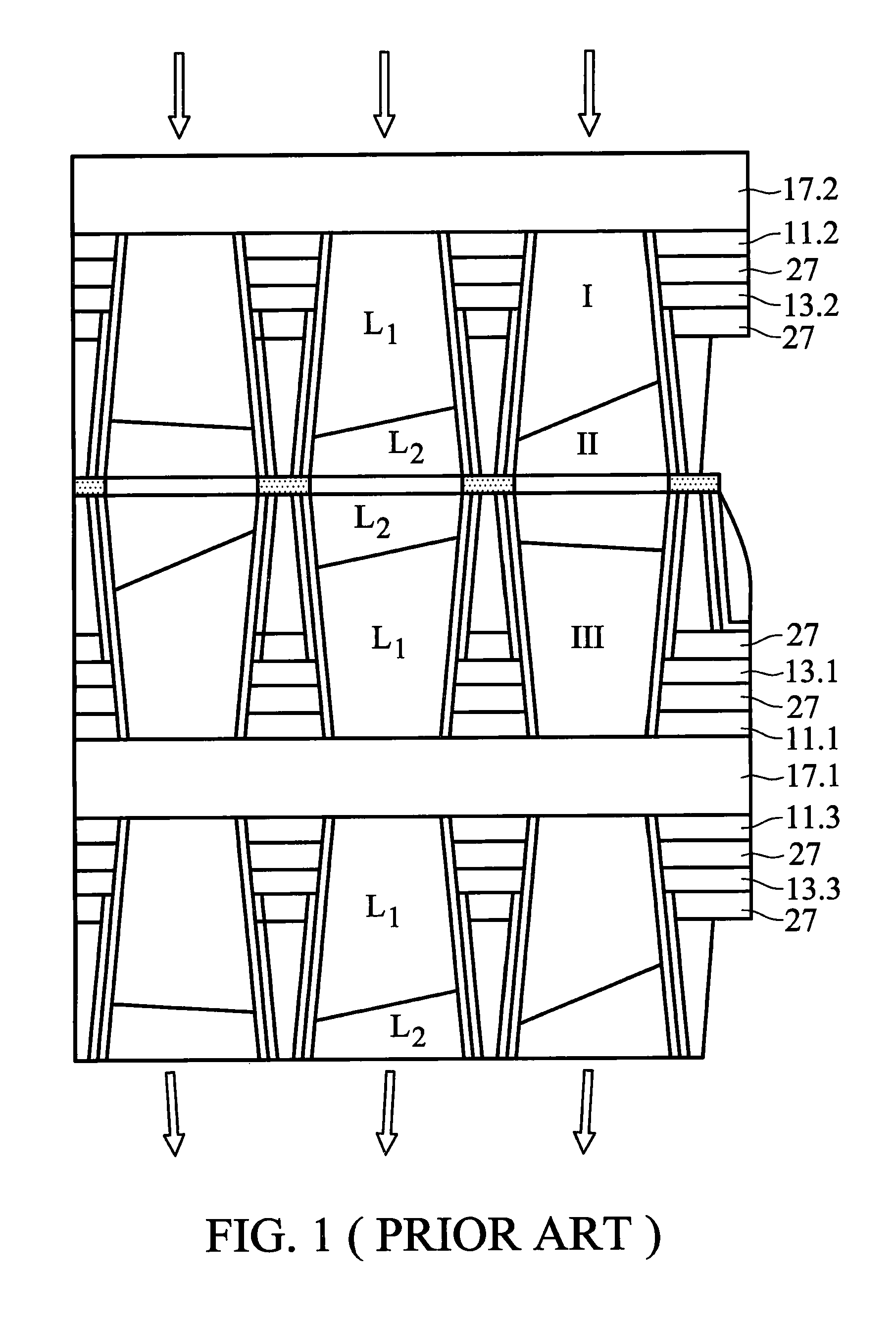
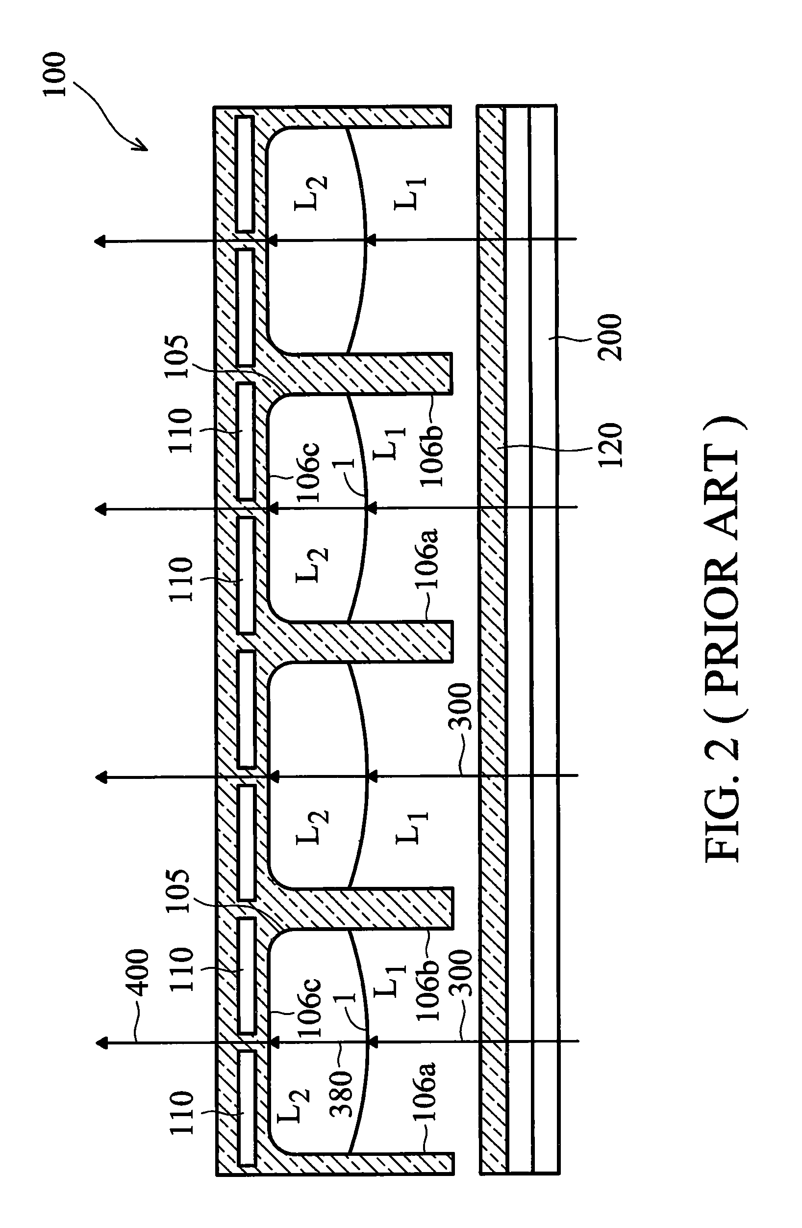
BACKGROUND OF THE INVENTION[0001]1. Field of the Invention[0002]The present invention relates to a three-dimensional (3D) image display device, and in particular relates to a naked-eye type 3D image display device, and an image display device, and electrically switchable light modulating cells thereof.[0003]2. Description of the Related Art[0004]In Nature 425, 383 (2003), Hayes et al. discloses a novel on / off switch method, which applies an electrowetting principle to control colored oils. This technology has several advantages such as high color saturation, high image response speed, and low energy consumption, as compared to conventional technologies. Therefore, electrowetting was soon applied in the display technology field thereafter.[0005]In U.S. Patent Publication No. 2009 / 0257111, a tunable optical array device includes a substrate on which a TFT tuning circuitry is disposed thereon for controlling an upper layered cell array, as shown in FIG. 1. Two incompatible fluids havin...

Claims


Application Information

Patent Timeline
Patent Type & Authority Patents(United States)
IPC IPC(8): G02B26/02G02B30/28
CPCG02B26/005G02B27/225Y10T29/4998G02B30/28
Inventor LEE, CHIA-YENHSU, CHING-TUNGTSAI, MING-WEIWANG, YEONG-FENGCHOU, YEN-ILIANG, RONG-CHANG
Owner DELTA ELECTRONICS INC
Learn More