
III-nitride integrated schottky and power device

a technology of nitride and integrated schottky, which is applied in the direction of semiconductor devices, pulse techniques, electronic switching, etc., can solve the problems of one or both devices breaking and high voltag

Active Publication Date: 2006-08-10
INFINEON TECH AMERICAS CORP
View PDF3 Cites 85 Cited by
  • Summary
  • Abstract
  • Description
  • Claims
  • Application Information

AI Technical Summary

Benefits of technology

The present invention provides a power device that includes a synchronous semiconductor rectifier (SSR) for use in high-speed power supplies or boost circuits. This device helps improve efficiency by allowing for better timing between different components within the circuit. It also reduces noise levels and improves overall performance. Additionally, this device has been designed with safety standards in mind, ensuring safe operation even under extreme conditions.

Problems solved by technology

The patent text discusses the use of III-nitride power semiconductor devices in power supply applications. However, current methods for switching between power switches can result in high voltage levels that can damage the devices. The technical problem addressed by the patent is to provide a III-nitride power device that can be used in a power supply without succumbing to the drawbacks of previous methods. Additionally, the patent aims to provide a power supply circuit that includes a III-nitride power device that does not suffer from the drawbacks of previous methods.

Method used


Image

  • III-nitride integrated schottky and power device
  • III-nitride integrated schottky and power device
  • III-nitride integrated schottky and power device

Examples


Embodiment Construction

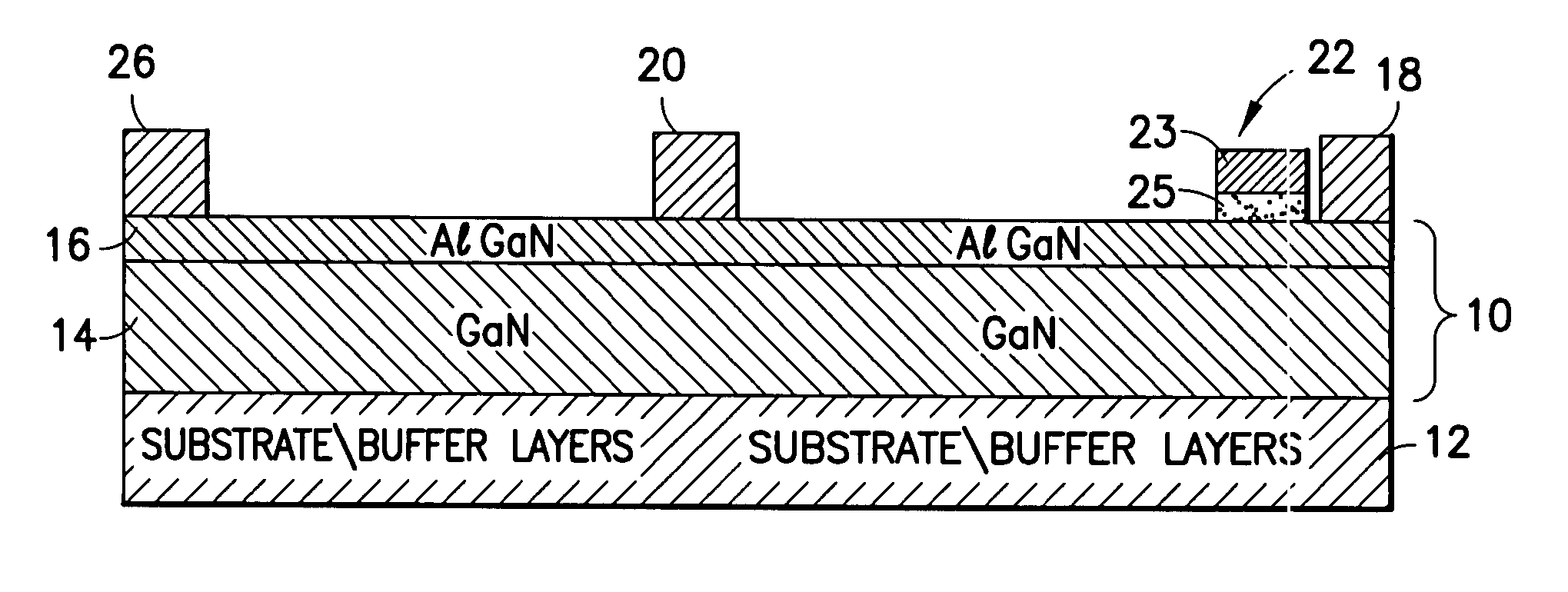
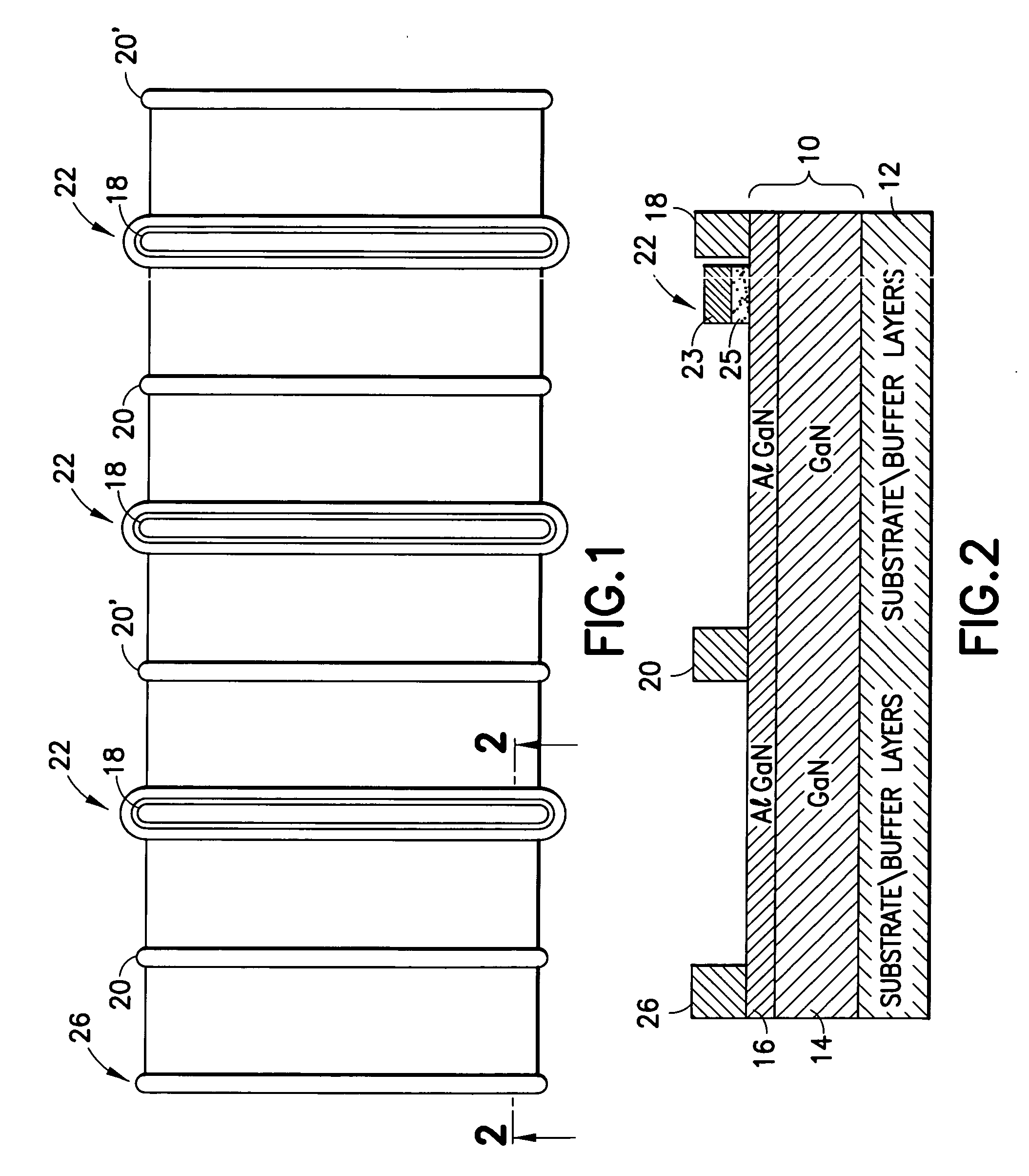
[0018] Referring to FIGS. 1 and 2, a power semiconductor device according to the first embodiment of the present invention includes a III-nitride based heterojunction 10 disposed over a support body 12. Heterojunction 10 includes a first III-nitride semiconductor body 14, and a second III-nitride semiconductor body 16 over first III-nitride semiconductor body 14. A first power electrode 18 (i.e. source electrode) and a second power electrode 20 (i.e. drain electrode) are electrically connected to second III-nitride semiconductor body 16 through a direct ohmic connection or any other suitable means. A gate structure 22 is disposed between first power electrode 18 and second power electrode 20 over second III-nitride semiconductor body 14. In the preferred embodiment of the present invention, gate structure 22 includes gate electrode which is capacitively connected to second III-nitride semiconductor layer 16 through gate insulation body 25. Alternatively, gate structure 22 may includ...


PUM


Abstract

A III-nitride power device that includes a Schottky electrode integrated with a power switch. The combination is used in power supply circuits such as a boost converter circuit.

Description


Claims


Application Information

Patent Timeline
Owner INFINEON TECH AMERICAS CORP
Features
  • Generate Ideas
  • Intellectual Property
  • Life Sciences
  • Materials
  • Tech Scout
  • Unparalleled Data Quality
  • Higher Quality Content
  • 60% Fewer Hallucinations
Learn More