Continuous automatic rack loader

a rack loader and automatic technology, applied in the field of sausage preparation, can solve the problems of difficult for a worker to keep a sausage completely straight, bending and sagging create unsightly blemishes in the collagen casing, and the method of sausage manufacturing is difficult to achiev

Active Publication Date: 2006-08-10
POLY CLIP SYST
View PDF5 Cites 6 Cited by
  • Summary
  • Abstract
  • Description
  • Claims
  • Application Information

AI Technical Summary

Benefits of technology

[0007] Briefly, the preferred embodiment of the present invention is a system for making and loading sausages, comprising a sausage stuffer/clipper; a rack loader; and a rack having a plurality of platforms; in which the rack loader comprises a conveyor rotating on a frame in a path and having a loading side and an unloading side, the sausage stuffer/clipper being located adjacent the loading side and the rack being located adjacent the unloading side, a plurality of gimbals projecting from the conveyor, a plurality of trays each having an open first end adapted to receive a sausage from the stuffer/clipper on the loading side and each being suspended from a one of the plurality of gimbals, and an arm within a cylinder mounted at a first end on the frame, the arm movable in a reciprocating manner from a first position proximal to the fr

Problems solved by technology

Problems arise in this method of manufacture of sausages.
Accordingly, it is difficult for a worker to keep a sausage completely straight, as a worker who supports a, for example, three-foot-long sausage with two hands will often find the sausage bending or sagging in the middle.
Bending and sagging create unsightly blemishes in the collagen casing, displeasing to consumers.
Additionally, the manual nature of the operation means some percentage of sausages will be dropped and therefore ruined.

Method used


Image

  • Continuous automatic rack loader
  • Continuous automatic rack loader
  • Continuous automatic rack loader

Examples


Embodiment Construction

[0016] While the invention may be susceptible to embodiment in different forms, there is shown in the drawings, and herein will be described in detail, specific embodiments with the understanding that the present disclosure is to be considered an exemplification of the principles of the invention, and is not intended to limit the invention to that as illustrated and described herein.

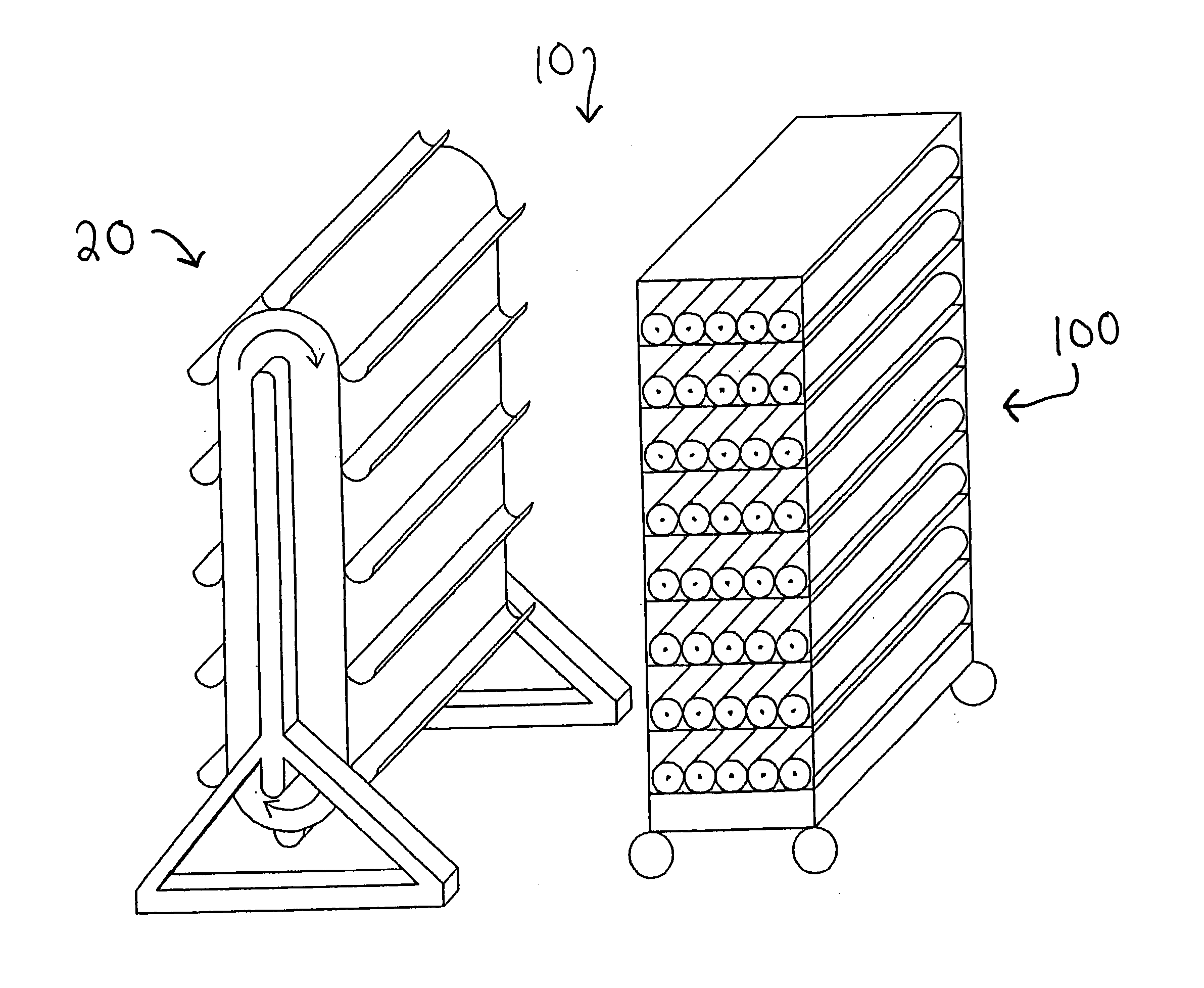
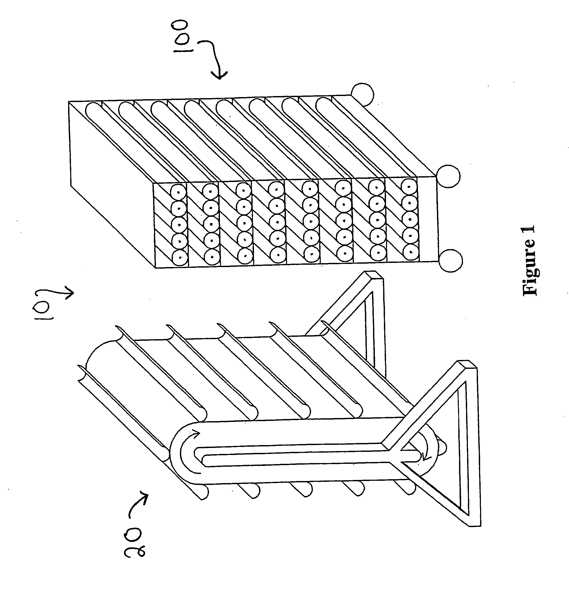
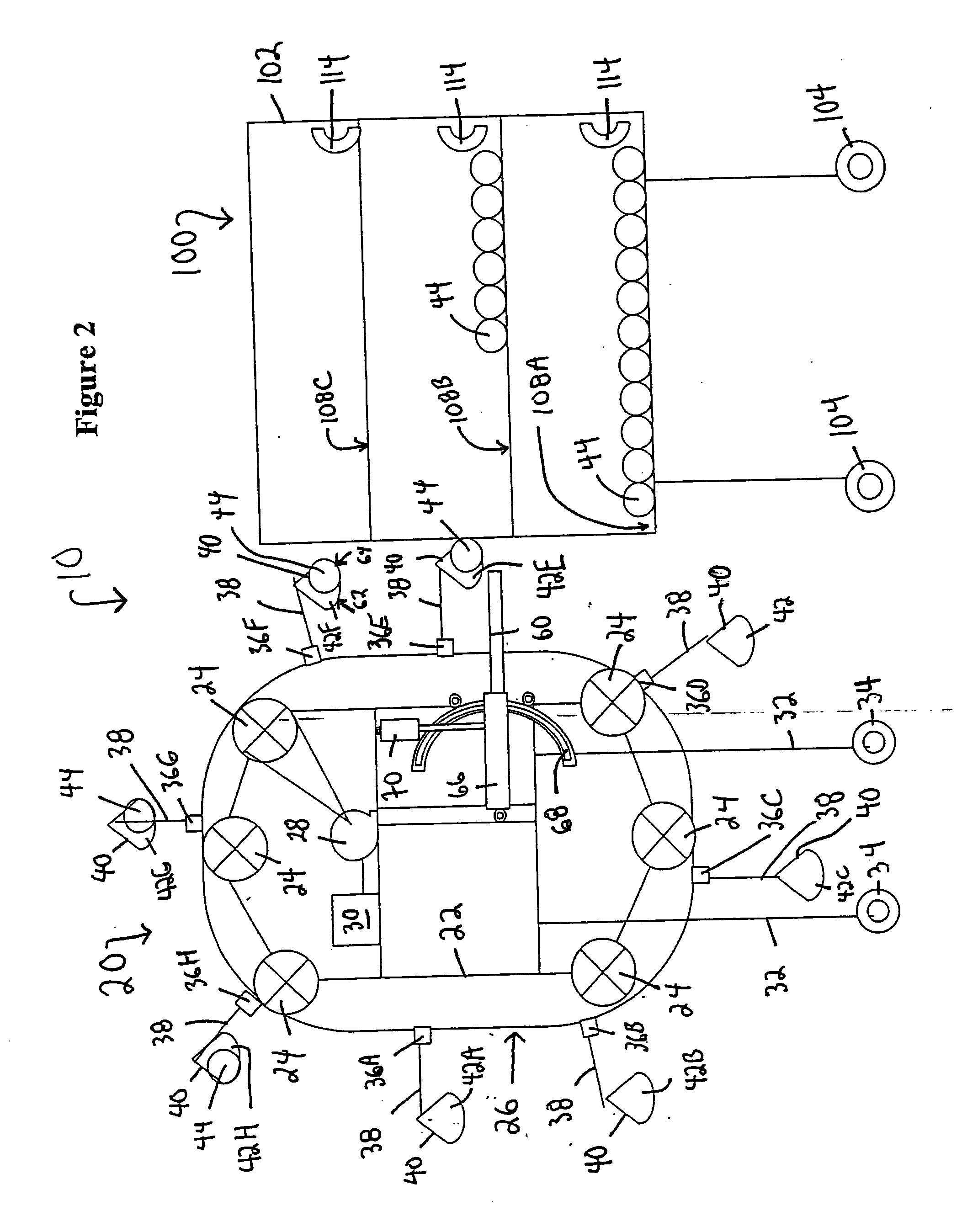
[0017] The conveyor system 10 of the preferred embodiment of the present invention is shown in FIGS. 1 and 2. Loader 20 has a frame 22 carrying a plurality of wheels 24, on which travels rotating conveyor 26 in a generally oval path. Motor 28 drives the conveyor 26 in, as seen from the view of FIG. 1, a clockwise direction. Motor 28 is preferably a step-motor. Preferably, a programmed logic controller, PLC 30, controls motor 28, although another type of controller or a manual control is possible. Frame 22 is fastened to legs 32, which preferably are fixed to casters 34 for ease of movement. Since the lo...


PUM


Abstract

An apparatus for automatically delivering raw sausages to a smokehouse rack is described. A continuous rotating conveyor holds a plurality of half-tubular trays hung on gimbals. Sausages are extruded into a tray at a loading station, and the tray is carried around by the conveyor to an unloading station, where an arm causes the tray to tilt and to roll the sausage onto a smokehouse rack.

Description

PRIORITY [0001] This application claims the benefit of U.S. provisional application Ser. No. 60 / 651,809, filed on Feb. 10, 2005.BACKGROUND OF THE INVENTION [0002] This invention relates generally to the field of sausage preparation. Specifically, this invention relates to loaders used to hold sausages during smoking or cooking. [0003] Sausages are made by filling a tubular casing, such as one made from a collagen film, with a pasty product. The pasty product is usually a mixture of minced meat and seasonings, but can also include vegetarian products. Often, the tubular casing is itself wrapped in a tubular netting. The sausage is then processed by smoking, cooking, aging, steaming, or other finishing operation. The netting is usually left on the sausage during the finishing operation and may or may not be removed prior to sale to the consumer. An illustrative process of making sausages is described in U.S. Pat. No. 5,024,041 to Urban, Process for Filling Tubular Casings. [0004] As t...

Claims


Application Information

Patent Timeline
IPC IPC(8): A22C11/00
CPCA22C11/008A22C15/001A22C15/007
Inventor HASCHKE, EGGOPINTO, ROBERT
Owner POLY CLIP SYST
Why Eureka
Try Eureka