

Glazing system
a self-locking mechanism and glazing technology, applied in the direction of glass pane fixing, doors/windows, building components, etc., can solve the problems of laborious, eventually expensive, complicated work, etc., and achieve the effect of fast glazing and easy installation on si
- Summary
- Abstract
- Description
- Claims
- Application Information
AI Technical Summary
Benefits of technology
Problems solved by technology
Method used
Image

Examples
Embodiment Construction
[0001] 1. Technical Field
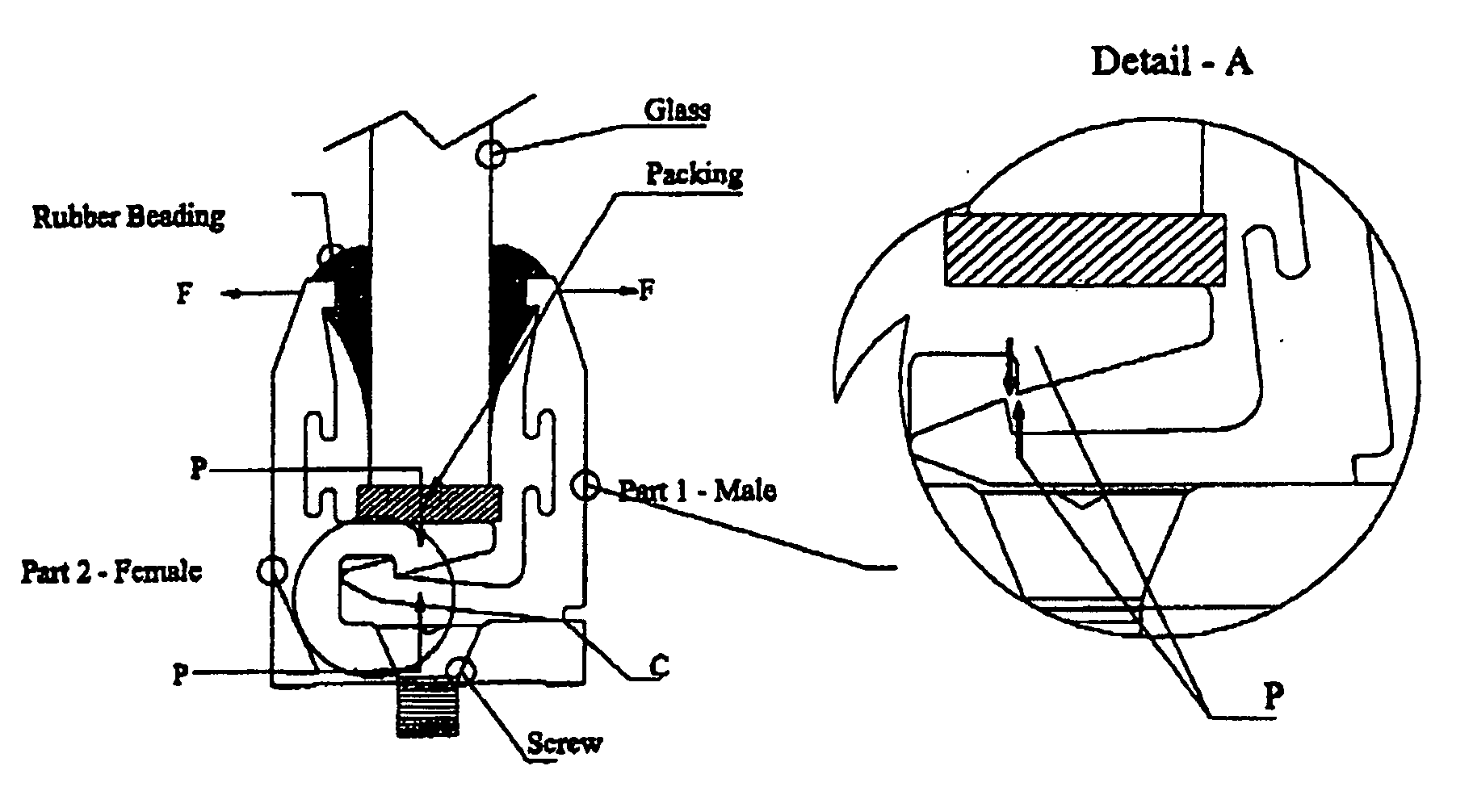
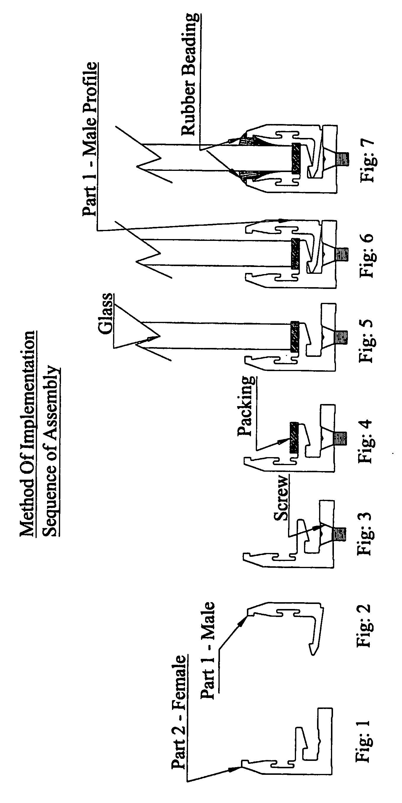
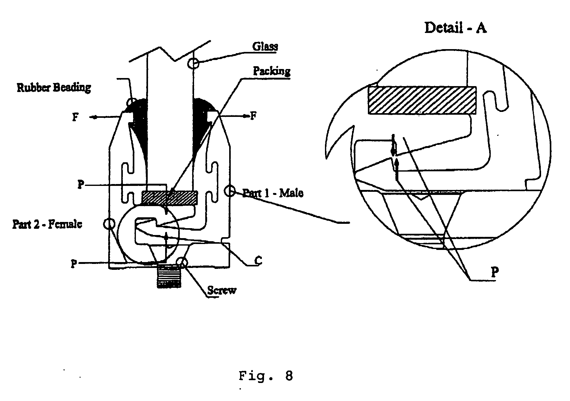
[0002] The current invention relates to a unique and compact self locking mechanism, composed of two aluminum profiles designed in such a way to self lock when Glass is placed on the female profile and the male profile is inserted and the mechanism further tightens grip on the glass edges when pushed in a grooved rubber (which is mandatory for glazing to avoid touching metal, to allow expansion and to absorb impacts).
[0003] 2. Technical Background
[0004] U.S. Pat. No. 5,007,221 entitled “A SNAP-IN GLAZING POCKET FILLER” is disclosed a snap-in pocket filler for use with a structural frame member having an unused Glazing Pocket” or to be used as a Gap Filler on Aluminum Profiles to cover the unused area for aesthetic reason.
[0005] It was noticed that a proper glazing system was lacking in the market to meet the increasing demand for thicker Glazing (e.g.: shop fronts & partitions) and it has become a necessity for those skilled in the art to develop a syste...
PUM
 Abstract
Description
Claims
Application Information