Control mechanism for controlling width of two cutting blades

a control mechanism and cutting blade technology, applied in the direction of metal working apparatus, secateurs, etc., can solve the problems of difficulty in finding, conventional control devices exposed on the outside of scissors, and might be tangled, and conventional control devices can also be activated unintentionally

Inactive Publication Date: 2006-08-31
NUSHARP
View PDF8 Cites 17 Cited by
  • Summary
  • Abstract
  • Description
  • Claims
  • Application Information

AI Technical Summary

Benefits of technology

[0004] The present invention relates to a pair of scissors which comprises a first part having a first handle and a first blade which is connected to an end of the first handle. A first pivotable hole is defined in the first part and located between the first handle and the first blade. The first part has a connection hole. A second part has a second handle and a second blade which is connected to an end of the second handle. A second pivotable hole is defined in the second part and located between the second handle and the second blade. The first and second parts are pivotably connected ...

Problems solved by technology

Most of the conventional control device includes many tiny parts which are assembled in a complicated way.
During assembling, the parts often jump out because of the spring and are difficult to b...

Method used


Image

  • Control mechanism for controlling width of two cutting blades
  • Control mechanism for controlling width of two cutting blades
  • Control mechanism for controlling width of two cutting blades

Examples


Embodiment Construction

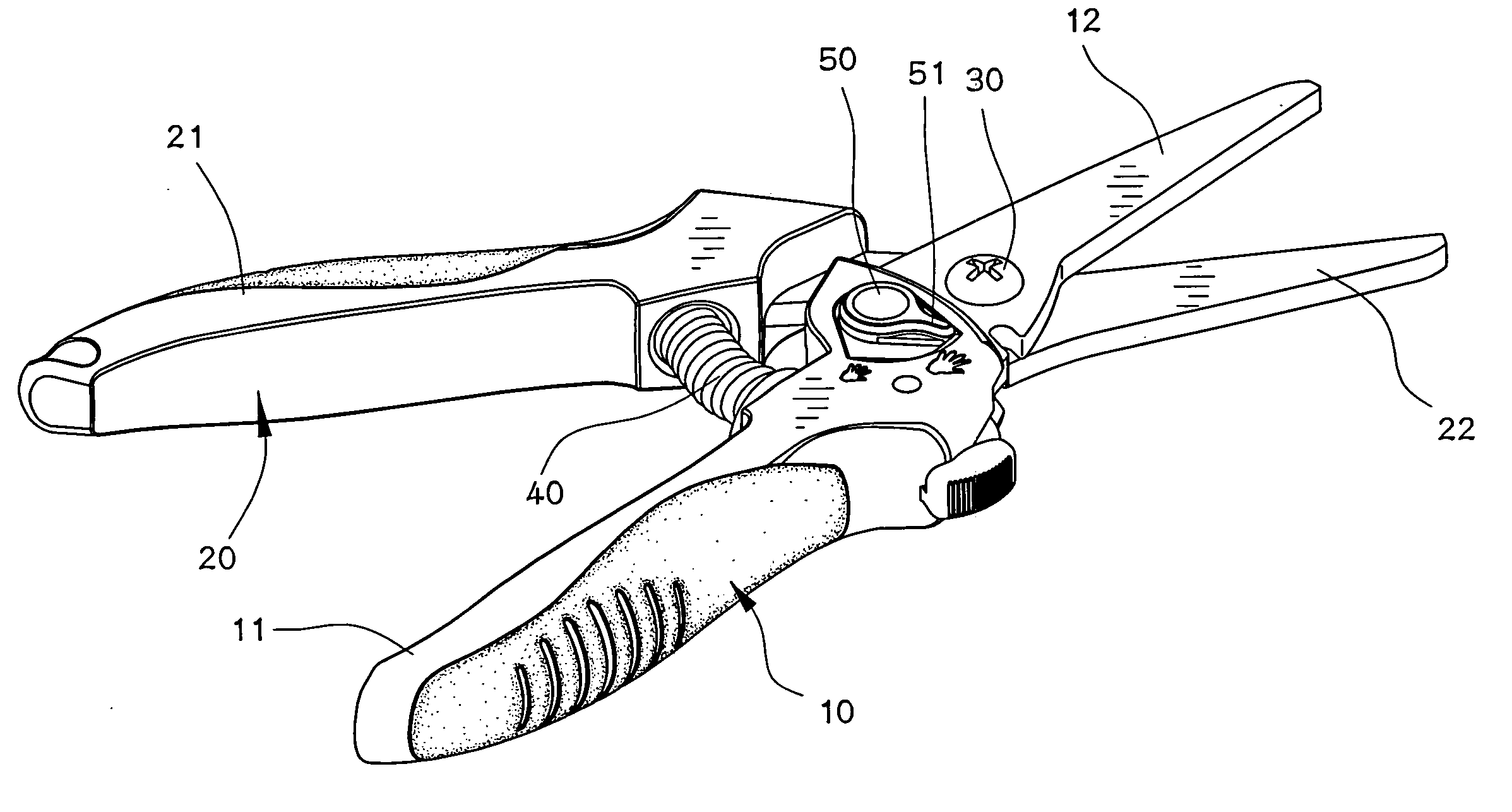
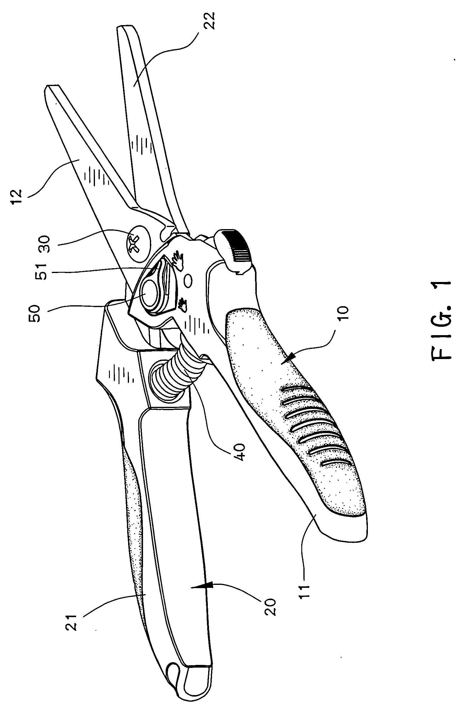
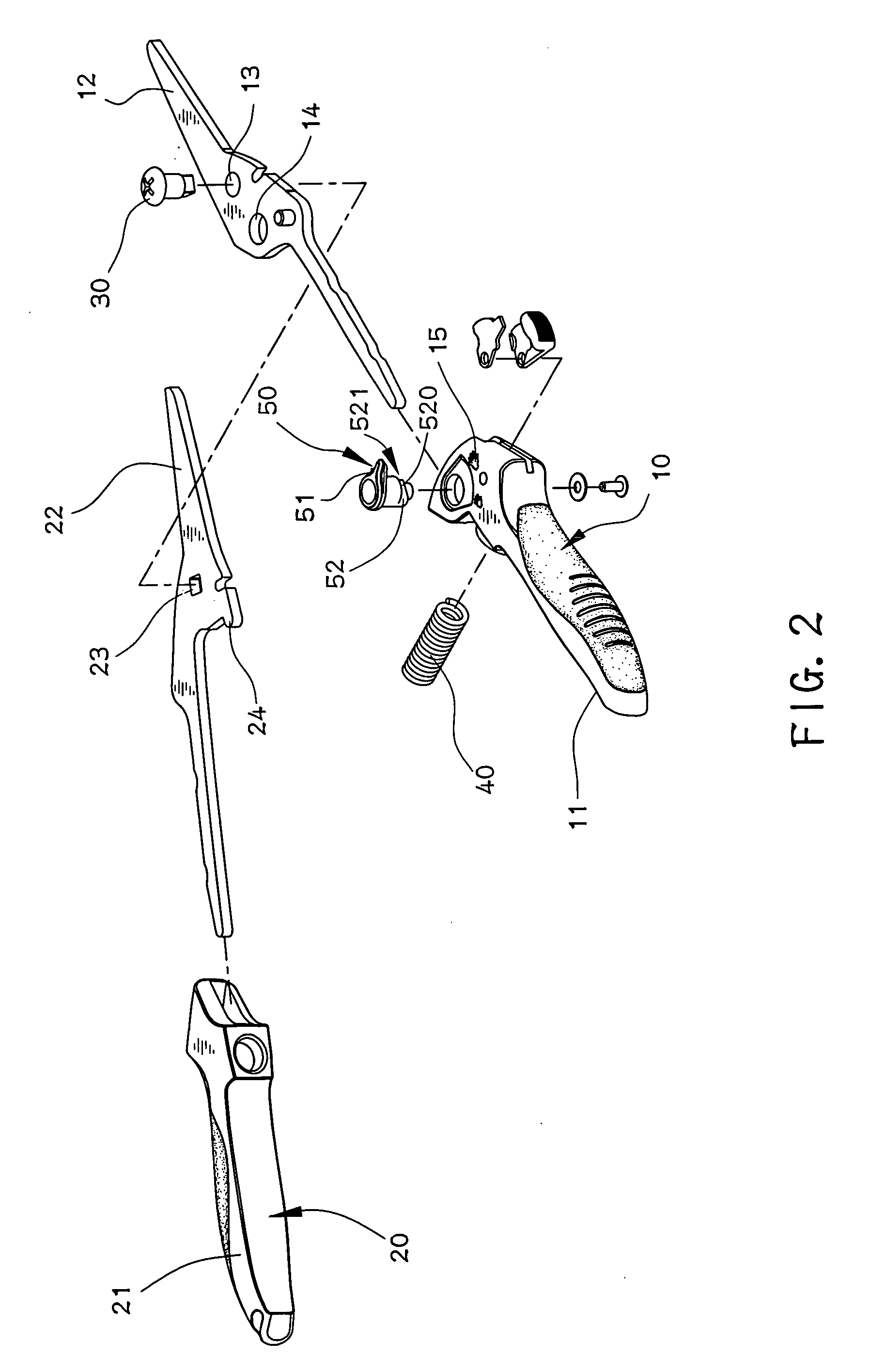
[0013] Referring to FIGS. 1 to 3, the scissors of the present invention comprises a first part 10 having a first handle 11 which can be a grip mounted to the first handle 11, and a first blade 12 which is connected to an end of the first handle 11. A first pivotable hole 13 is defined in the first part 10 and located between the first handle 11 and the first blade 12. The first part 10 has a connection hole 14 which is located close to the first handle 11 than the first pivotable hole 13.

[0014] A second part 20 has a second handle 21 which can be a grip mounted to the second handle 21, and a second blade 22 which is connected to an end of the second handle 21. A second pivotable hole 23 is defined in the second part 20 and located between the second handle 21 and the second blade 22. A pin 30 extends through the first and second pivotable holes 13, 23 so as to pivotably connect the first part 10 to the second part 20. The second part 20 has a stop 24 extending from an inside thereo...


PUM


Abstract

A pair of scissors includes a first part which is pivotably connected to a second part. A stop extends from an inside of the second part. A control member rotatably extends through a connection hole in the first part and includes a plurality of engaging surfaces which have different radial heights so that the stop is engaged with one of the engaging surfaces to set the desired width between two blades of the first and second parts.

Description

FIELD OF THE INVENTION [0001] The present invention relates to a control mechanism for controlling width between two cutting blades of pruning scissors, wherein the mechanism is located between the two handles and includes multiple controlling stages. BACKGROUND OF THE INVENTION [0002] A conventional pair of scissors or pruning scissors generally includes two handles which are pivotably connected with each other and two cutting blades are integrally connected to two respective ends of the handles so that when closing the two handles toward each other, the two cutting blades are moved toward each other to cut an object therebetween. A locked or control device is connected to the conventional pruning scissors to set the positions of the two blades, such as to maintain the two blades at close position. Most of the conventional control device includes many tiny parts which are assembled in a complicated way. The parts include a spring, a rack member, a pin and a ratchet member, all of w...

Claims


Application Information

Patent Timeline
IPC IPC(8): B26B13/00
CPCA01G3/02B26B13/22B26B13/16
Inventor JOU, TITAN
Owner NUSHARP
Why Eureka
Try Eureka