
Hand-actuated articulating surgical tool

a technology of articulating surgical tools and hands, which is applied in the field of surgical instruments, can solve the problems of inability to bend within the body to reach the backside of the human heart, the disadvantage of extensive sterilization of internal components of the tools, and the limited accessibility of current laparoscopic surgical tools. achieve the effect of simple and inexpensive sterilization and reus

Inactive Publication Date: 2006-08-31
CAREFUSION 2200 INC
View PDF99 Cites 3 Cited by
  • Summary
  • Abstract
  • Description
  • Claims
  • Application Information

AI Technical Summary

Benefits of technology

The present invention provides an apparatus for performing minimally invasive surgery while allowing articulation of the tool within the patient's body. The surgical tool is simple and inexpensive to sterilize and reuse. The invention also allows a surgeon to operate on a portion of an organ, for example, the heart, without the need for arresting the entire organ. The surgical device includes a controller, manipulator, and slave that work together to manipulate the surgical tip in response to hydraulic control signals. The device can also include an articulating portion that allows for bending as desired.

Problems solved by technology

Current laparoscopic surgical tools are limited in accessibility of certain regions of the human body.
Existing tools can perform invasive surgery without making a substantial incision, but these tools are incapable of bending within the body to reach, for example, the backside of the human heart.
These tools have the disadvantage of requiring extensive sterilization of the internal components.
The cleaning of internal metal cables can be a lengthy and expensive process.
Alternatively, disposable components may be used with a substantial increase in recurring costs.
This requires additional equipment such as the artificial support system, substantially increasing the cost of the procedure.

Method used


Image

  • Hand-actuated articulating surgical tool
  • Hand-actuated articulating surgical tool
  • Hand-actuated articulating surgical tool

Examples


Embodiment Construction

[0028] Certain embodiments of the invention will now be described in detail with reference to the figures.

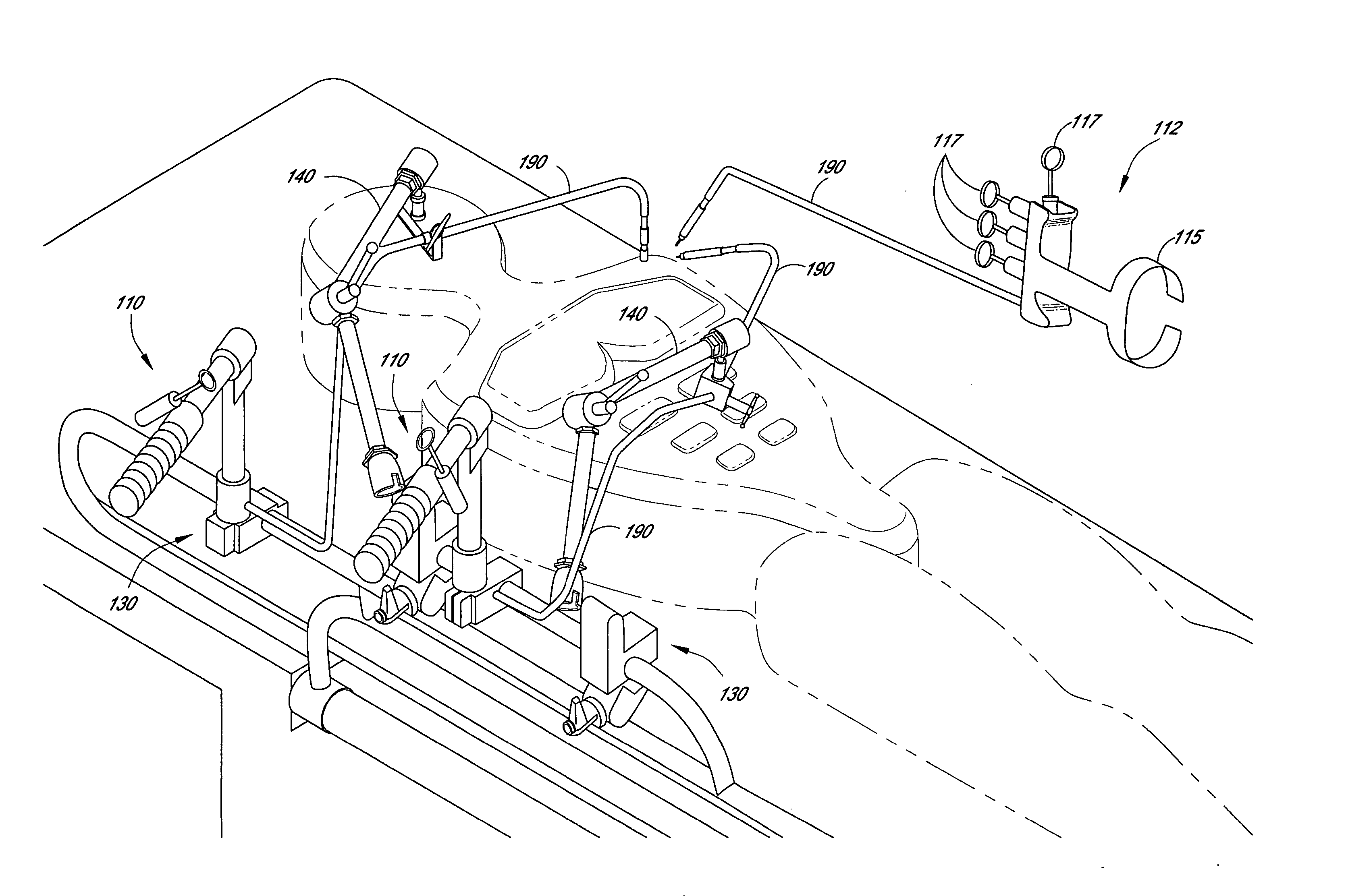
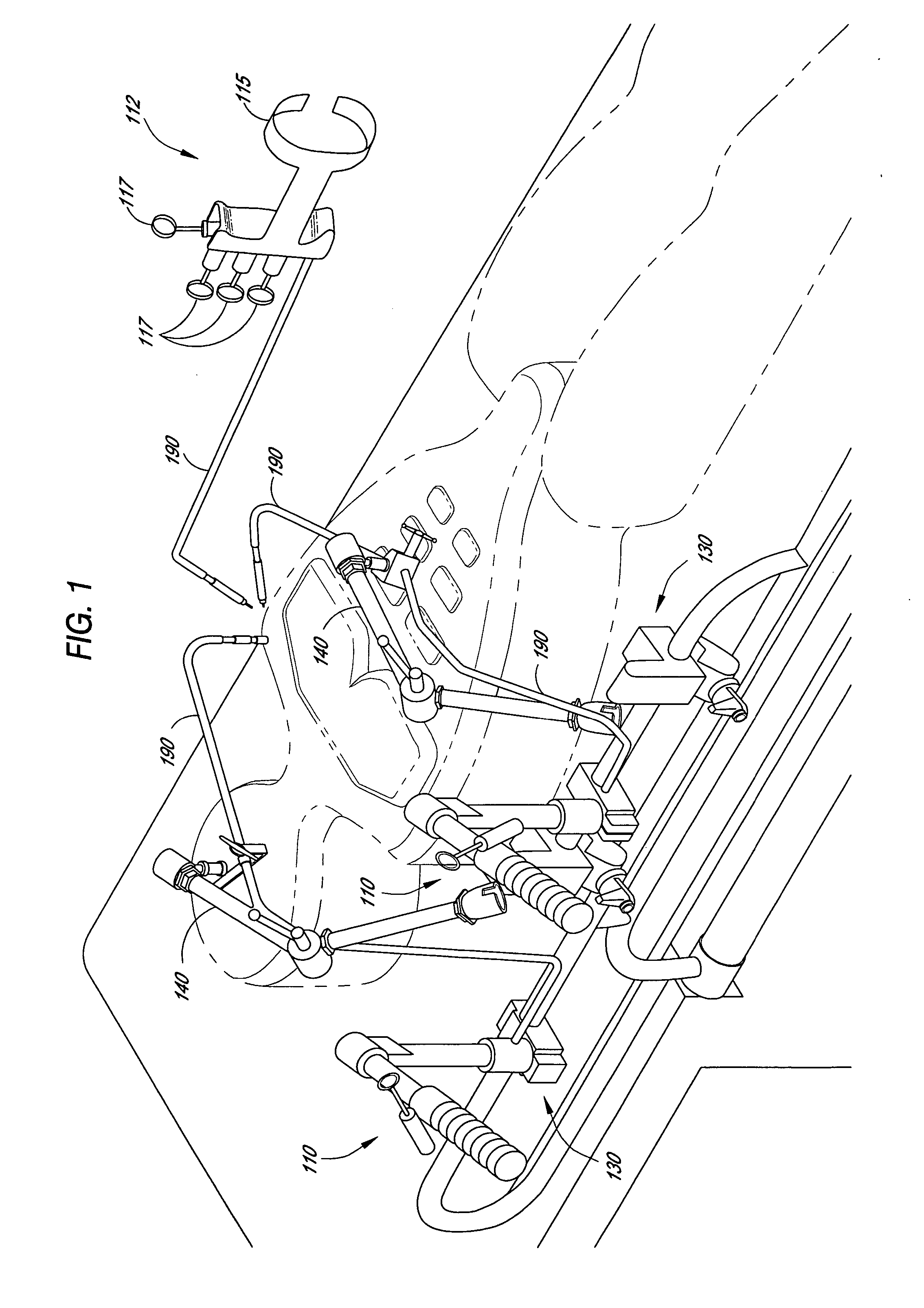
[0029]FIG. 1 shows a surgical tool according to the present invention. The tool has a control portion 110, 112 at the proximal end of the device and a slave portion 120 at the distal end of the device. As used herein, “proximal” refers to the part of the device that remains outside the patient's body, closest to the user. “Distal” refers to the end inserted into the patient, farthest away from the user. As with a specific component of the device, “proximal” refers to the part of the component closest to the proximal end of the device, whereas “distal” refers to the part of the component closest to the distal end of the device. An intermediate portion 190 lies between the control portion 110 and the slave portion 120. The “slave portion,” or the “distal end of the device,”120 is the portion of the device comprising the slave modules, i.e., the extend module, the bend module, the...


PUM


Abstract

A double cylinder system is disclosed, comprising at least one controller being adapted to transmit hydraulic control signals; at least one slave being in fluid communication with the controller and being configured to respond to the hydraulic control signals transmitted by the controller; and at least one control line providing hydraulic communication between the controller and the slave. Also disclosed is a surgical device, comprising at least one controller located at a proximal end of the device, the controller being adapted to transmit hydraulic control signals; at least one manipulator, the manipulator being configured to be controlled by a human hand and to actuate the controller; at least one slave located at a distal end of the device, the slave being in fluid communication with the controller and being configured to respond to the hydraulic control signals transmitted by the controller; and at least one control line providing hydraulic communication between the controller and the slave.

Description

RELATED APPLICATIONS [0001] This application is a continuation of U.S. application Ser. No. 10 / 996,872, filed on Nov. 23, 2004, by Doyle et al., and entitled “HAND-ACTUATED ARTICULATING SURGICAL TOOL,” which in turn is a continuation of U.S. application Ser. No. 10 / 388,795, filed on Mar. 12, 2003, by Doyle et al., and entitled “HAND-ACTUATED ARTICULATING SURGICAL TOOL,” which in turn is a continuation of U.S. application Ser. No. 09 / 910,482, filed on Jul. 18, 2001, by Doyle et al., and entitled “HAND-ACTUATED ARTICULATING SURGICAL TOOL,” now U.S. Pat. No. 6,607,475, issued on Aug. 19, 2003, which in turn claims priority to the U.S. Provisional Application Ser. No. 60 / 219,593, filed Jul. 20, 2000, by Doyle et al., and entitled “HAND-ACTUATED ARTICULATING SURGICAL TOOL,” all of which are incorporated by reference herein in their entirety, including any drawings.FIELD OF THE INVENTION [0002] The invention relates generally to surgical instruments. More particularly, the invention relat...

Claims


Application Information

Patent Timeline
Patent Type & Authority Applications(United States)
IPC IPC(8): A61B17/00A61B19/00
CPCA61B19/22A61B2017/00539A61B2019/306A61B34/70A61B2090/036A61B2017/00398A61B2017/2829A61B2017/2908A61B2017/2927A61B2017/2932A61B2017/2944A61B2017/2948A61B34/37A61B34/35A61B2017/2931A61B17/00
Inventor DOYLE, MARK C.CAPUTO, JIMMY C.
Owner CAREFUSION 2200 INC
Learn More