

Access catheter having dilation capability and related methods
- Summary
- Abstract
- Description
- Claims
- Application Information
AI Technical Summary
Benefits of technology
Problems solved by technology
Method used
Image

Examples
Embodiment Construction
[0040] Reference will now be made in detail to the exemplary embodiments consistent with the present invention, examples of which are illustrated in the accompanying drawings. Wherever possible, the same reference numbers will be used throughout the drawings to refer to the same or like parts.
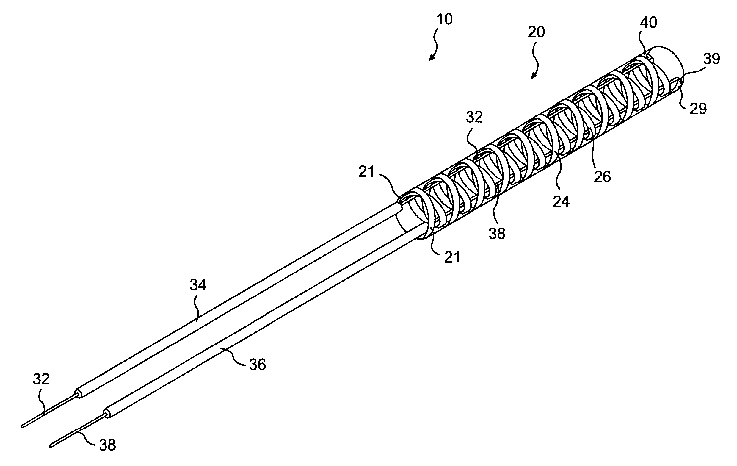
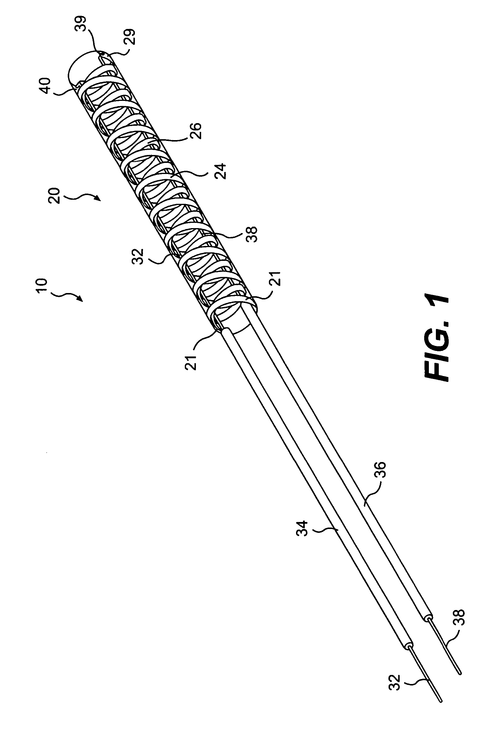
[0041]FIG. 1 illustrates a distal portion of a medical device, such as an access catheter 10 having a dilation mechanism for dilating, for example, a portion of the urinary tract (e.g., ureter), according to an exemplary embodiment of the invention. While the invention will be described in connection with a particular urology application (i.e., stone removal in the urinary tract), embodiments of the invention may be applied to, or used in connection with, other numerous medical and non-medical applications. For example, embodiments of the present invention may be used to dilate, expand, and / or repair occluded blood vessels, gastrointestinal tracts, or other body lumens or cavities. Some embodi...
PUM
 Abstract
Description
Claims
Application Information