
Method and means for establishing access to the main parts in the nacelle on a wind turbine

a technology for wind turbines and nacelles, which is applied in the direction of wind turbines, liquid fuel engines, motors, etc., can solve the problems of difficult operation of nacelle cabriolets, relatively high cost of solutions, and relative high cost of operations, so as to facilitate the handling and fitting of the nacelle. , the effect of reducing weigh

Active Publication Date: 2015-05-14
ELEVATORRA IP APS
View PDF7 Cites 7 Cited by
  • Summary
  • Abstract
  • Description
  • Claims
  • Application Information

AI Technical Summary

Benefits of technology

The patent text describes a mechanism for lifting and displacing the cabriolet of a wind turbine without the need for a crane. This mechanism can be mounted on any wind turbine and easily removed after use. It allows the cabriolet to be displaced in a controlled movement without tipping over or falling off the rolls. The mechanism includes a counter hold or roll that limits the displacement of the cabriolet to the point where it comes into abutment with the front end of the cabriolet. This prevents the cabriolet from tilting over its center of gravity and ensures stability against wind gusts. However, the added weight of the guide transfer mechanism may not always be beneficial.

Problems solved by technology

This requires, however, the presence of a mobile crane, which is relatively expensive operation since the crane charged at the hourly rental.
In cases where there used winches for the transport of the heavy parts from the nacelle and the ground surface, the handling of the nacelle cabriolet be a difficult operation due the relatively bulky design of the cabriolet, hence the need to operate with alternative solutions.
However, such solutions require the installation of fixed installations in a nacelle, in which is already scarce space, and the solution is relatively expensive compared to the number of times where such installation is required.

Method used


Image

  • Method and means for establishing access to the main parts in the nacelle on a wind turbine
  • Method and means for establishing access to the main parts in the nacelle on a wind turbine
  • Method and means for establishing access to the main parts in the nacelle on a wind turbine

Examples


Embodiment Construction

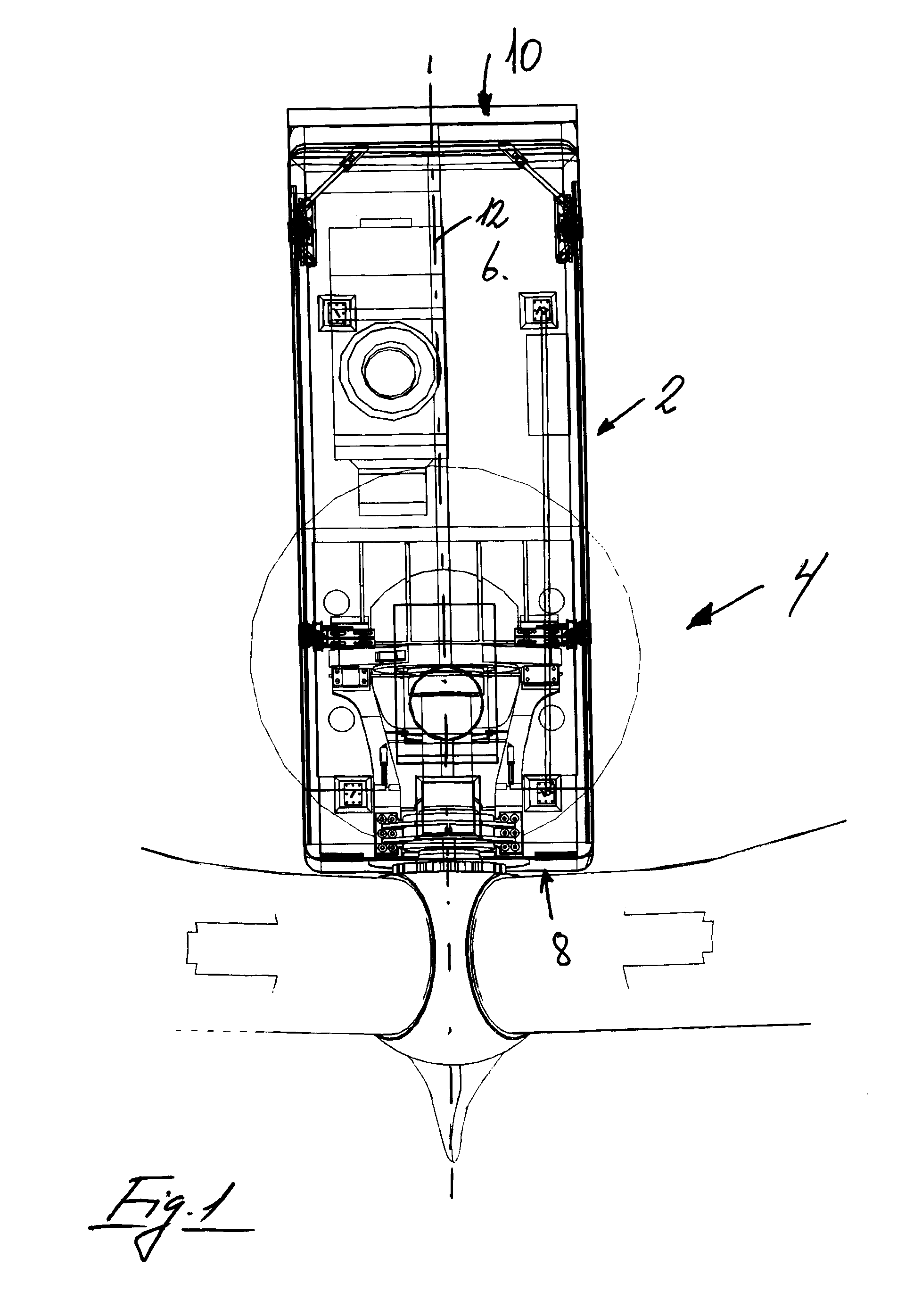
[0037]FIG. 1 is a view of the nacelle 2 on a wind turbine 4 seen from above where the cabriolet 6 is closed. The nacelle has a front end 8 and a rear end 10, and a center axis 12. In the view the cabriolet is made transparent.

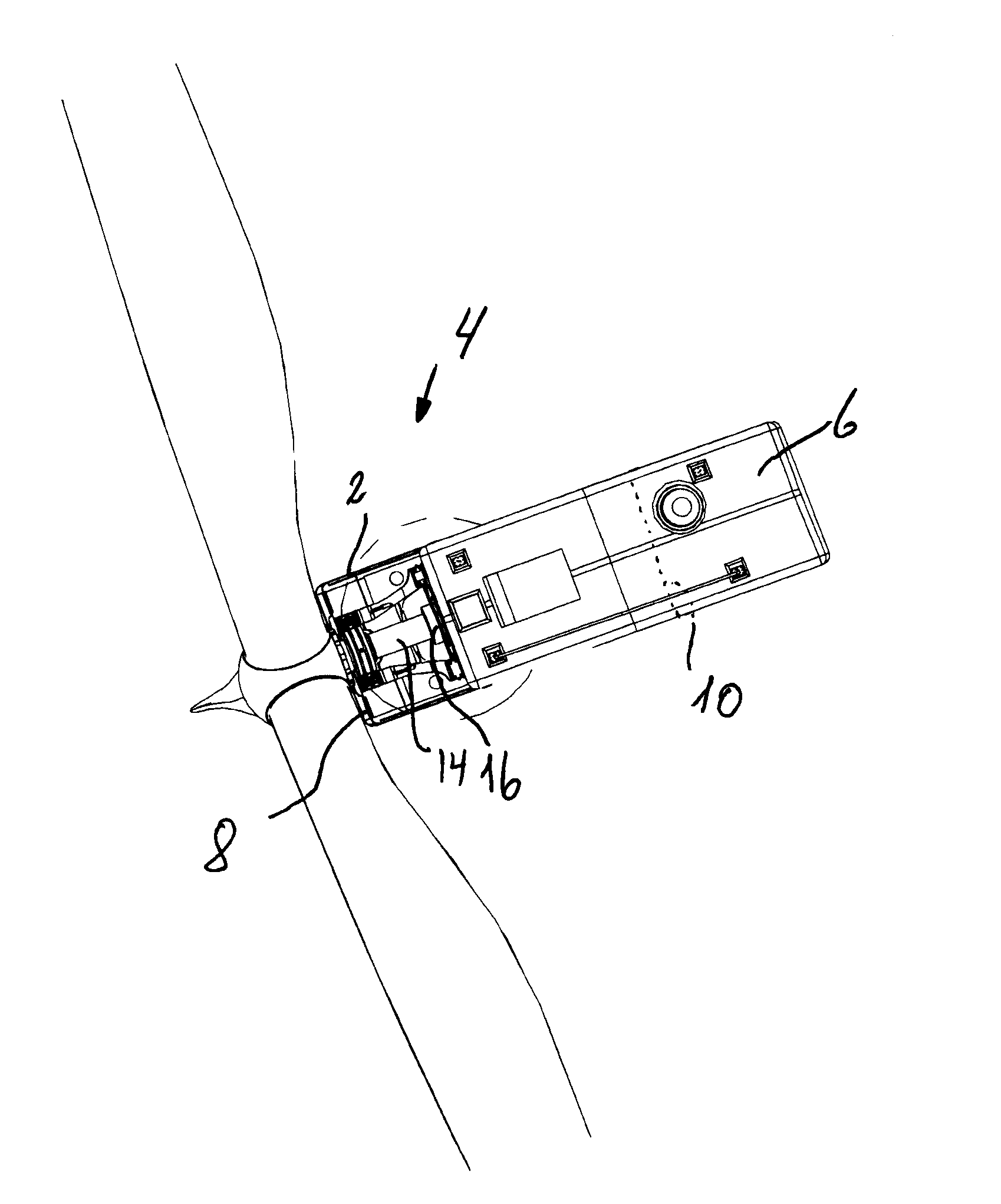
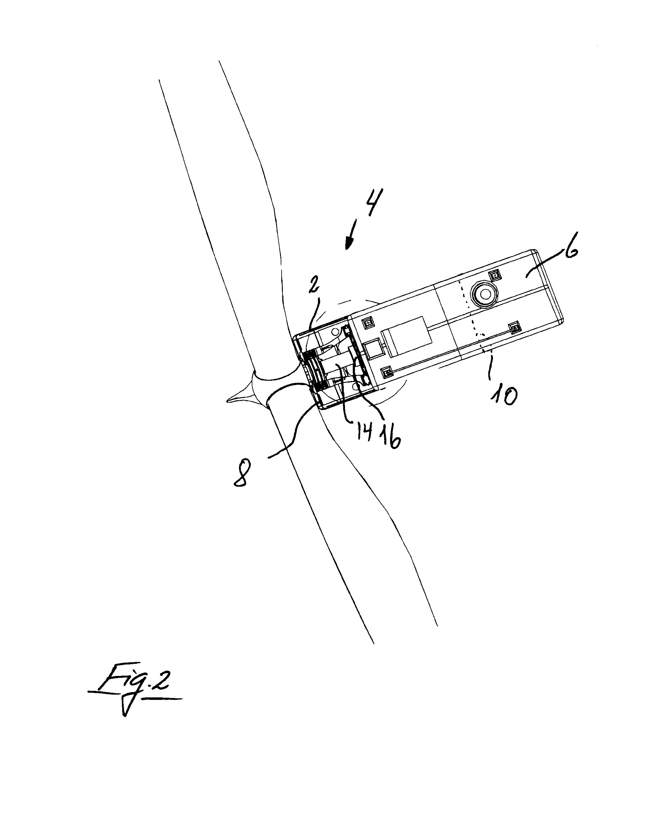
[0038]In FIG. 2, which is a view of the nacelle 2 shown in FIG. 1, the cabriolet is displaced backwards above the rear end 10 of the nacelle so the main shaft 14 and the gearbox 16 etc. of the wind turbine is exposed.

[0039]In FIG. 3, which is a perspective view of the nacelle shown in FIGS. 1 and 2, where the nacelle 2 and the cabriolet 6 is made transparent, appears how the cabriolet 6 is raised and carried respectively on a first set of guide transfer mechanisms 18, 18′, mounted on statically stable structural components 20 in the nacelle 2 close to the front end 8 of the nacelle, and a second set of guide transfer mechanisms 22, 22′ mounted on the parallel long sides 24, 24′ of the nacelle and with support beams 26 mounted on the rear side 28 of the nacelle....


PUM

PropertyMeasurementUnit
displacementaaaaaaaaaa
sizesaaaaaaaaaa
weightaaaaaaaaaa

Abstract

A method for establishing access for mounting and dismounting of main shafts, gearbox, generator and other main parts located in the nacelle of a wind turbine, where the cabriolet remains localized on the nacelle, and guide transfer mechanisms are provided for mounting inside the nacelle. The basic idea is that the cabriolet is lifted upon rolls or roll sets which form the guide transfer mechanisms upward facing support surfaces, and that the cabriolet is stabilized by displaceable counter holds which are displaced and locked in position above the downwards positioned mounting flange, upon which the cabriolet can be displaced on the rollers or roll sets to a partly cantilevered position over the rear end of the nacelle. By the method, service on larger wind turbines can be performed without using mobile cranes, which saves resources.

Description

BACKGROUND OF THE INVENTION[0001]1. Field of the Invention[0002]The present invention relates to a method for establishing access to the removal and installation of the main shaft, gearbox, generator and other main parts located in the nacelle of a wind turbine, the cabriolet remains localized on the nacelle, and guide mechanisms to perform the invention.[0003]2. Description of Related Art[0004]When carrying out service and repair work on large wind turbines, there is a need to be able to get access to mount and dismount vital and relatively heavy parts of the wind turbine, which is located in the interior of the nacelle. These parts are for example the main shaft, gearbox, generator and other major parts, which not can be transported up and down through the wind turbine tower, and where either the use of cranes or crane winch between the nacelle and a station on the ground, to handle said parts, which require that there is access to the nacelle from above. This access has so far be...

Claims


Application Information

Patent Timeline
Patent Type & Authority Applications(United States)
IPC IPC(8): F03D1/00
CPCF03D1/001F03D1/003F05B2240/14F03D13/10Y10T29/49826F03D80/50Y02E10/72
Inventor FENGER, PER
Owner ELEVATORRA IP APS
Learn More