Fluid dynamic bearing system

Active Publication Date: 2006-09-21
MINEBEAMITSUMI INC
View PDF16 Cites 30 Cited by
  • Summary
  • Abstract
  • Description
  • Claims
  • Application Information

AI Technical Summary

Benefits of technology

[0017] Another advantage of the invention is the possibility of attaching the bearing at both ends (top and bottom), in other words at the first and second bearing parts. Here, the third part preferably forms the rotating part of the bearing. The possibility of fixing the bearing at both ends is beneficial for applications that have stringent requirements regarding the smooth running of the bearings as, for example, in hard disk drive motors. The basic principle, however, can be equally applied to bearings fixed only at one end.
[0018] The bearing gap can be connected together in the regions of the two axial bearings by means of one or more recirculation channels provided in the third part. This aids the circulation of the bearing fluid within the bearing and supports the effectiveness of the dynamic seal due to improved pressure equalization in the bearing.
[0019] The bearing system is preferably a component of a spindle motor, as used, for example, in hard disk drives, the third part forming at least a part of the rotor of the spindle motor. For this kind of application, it is advantageous if the bearing system can be attached at both ends, i.e. at the first and/or second part.
[0020

Problems solved by technology

The ongoing miniaturization of hard disk drives is giving rise to new problems in their design and construction, particularly with regard to the design and construction of small drive motors and suitable bearing systems.
However, conventional solutions in the design of fluid dynamic hard disk drive bearings and methods for their manufacture are either impossible to a

Method used


Image

  • Fluid dynamic bearing system
  • Fluid dynamic bearing system
  • Fluid dynamic bearing system

Examples


Embodiment Construction

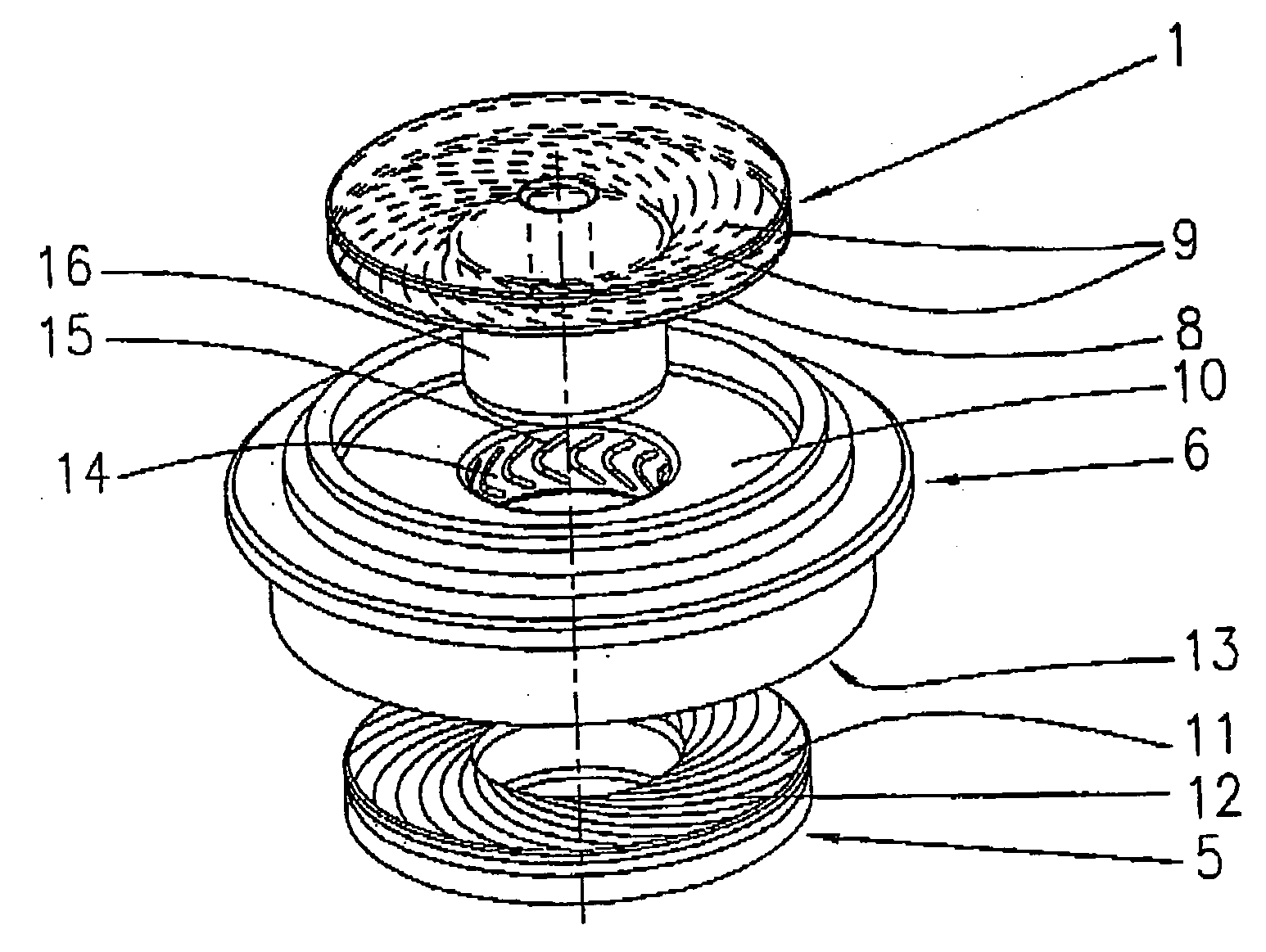
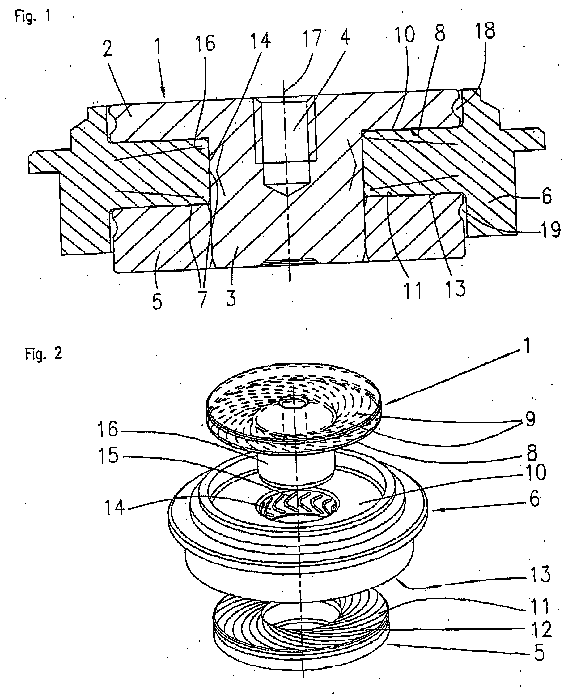
[0039]FIG. 1 shows the basic construction of a bearing according to the invention. The main distinctive feature of the bearing is its simple design and construction. In the version shown in FIG. 1, the bearing consists of only three parts. A first part 1 that has a disk-shaped section 2 and an adjoining cylindrical section 3 affixed concentrically with respect to a rotational axis 17. At least one tapped hole 4 to fasten the part to a housing or suchlike is provided concentric to the rotational axis 17 on part 1. A second annular part 5 is fixed to the cylindrical section 3 of the first part1 at a spacing to the disk-shaped section 2 in such a way that an annular space between the two parts 1 and 5 is formed. Section 2 of part 1 and bearing part 5 preferably have the same outside diameter. A third, substantially annular, part 6 is partially accommodated in the space and arranged there in such a way that it can rotate about the rotational axis 17 with respect to the first 1 and secon...


PUM


Abstract

The invention relates to a fluid dynamic bearing system having at least one stationary part and one rotating part that form a bearing gap filled with bearing fluid between the opposing bearing surfaces, at least one end of the bearing gap being open and sealed against the environment by a sealing means, pumping grooves being provided on at least two spatially separated bearing surfaces to generate hydrodynamic pressure and at least one supply volume connected to the bearing gap being available for the bearing fluid. The distinctive feature of the invention is that the sealing means are formed by pumping grooves that are disposed at the open end of the bearing gap on at least one of the bearing parts and designed in such a way that they generate a pumping action on the bearing fluid directed towards the interior of the bearing and, as a result, create a dynamic seal for the open end of the bearing. The bearing system itself is designed as a compact unit preferably consisting of only three parts.

Description

BACKGROUND OF THE INVENTION [0001] The invention relates to a fluid dynamic bearing system, particularly a small-scale fluid dynamic bearing system for spindle motors such as are employed, for example, in hard disk drives. PRIOR ART [0002] The ongoing miniaturization of hard disk drives is giving rise to new problems in their design and construction, particularly with regard to the design and construction of small drive motors and suitable bearing systems. Although roller bearing systems have mainly been used to date, fluid dynamic bearing systems are becoming increasingly popular due to their small-scale construction and higher precision. However, conventional solutions in the design of fluid dynamic hard disk drive bearings and methods for their manufacture are either impossible to apply or can only be applied with difficulty. The smaller the bearing systems get, the lower are their load-bearing capacity and stiffness, particularly in conventional designs. [0003] Another problem f...

Claims


Application Information

Patent Timeline
IPC IPC(8): F16C32/06
CPCF16C17/107F16C33/107F16C33/743F16C2370/12
Inventor ENGESSER, MARTINSCHWAMBERGER, STEFAN
Owner MINEBEAMITSUMI INC
Why Eureka
Try Eureka