Supercharge Your Innovation With Domain-Expert AI Agents!

Ratchet mechanism for ratchet tools

a ratchet tool and mechanism technology, applied in the field of ratchet mechanism for ratchet tools, can solve the problem of taking a lot of time to assemble the parts to be a ratchet tool

Inactive Publication Date: 2006-09-28
LEE CHANG CHUAN
View PDF8 Cites 6 Cited by
  • Summary
  • Abstract
  • Description
  • Claims
  • Application Information

AI Technical Summary

Benefits of technology

[0006] The present invention will become more obvious from the following description when taken in connection with the accompanying drawings which show, for purposes of illustration only, a preferred embodiment in accordance with the present invention.

Problems solved by technology

In other words, it takes a lot of time to assemble the parts to be a ratchet tool 7.

Method used


Image

  • Ratchet mechanism for ratchet tools
  • Ratchet mechanism for ratchet tools
  • Ratchet mechanism for ratchet tools

Examples


Embodiment Construction

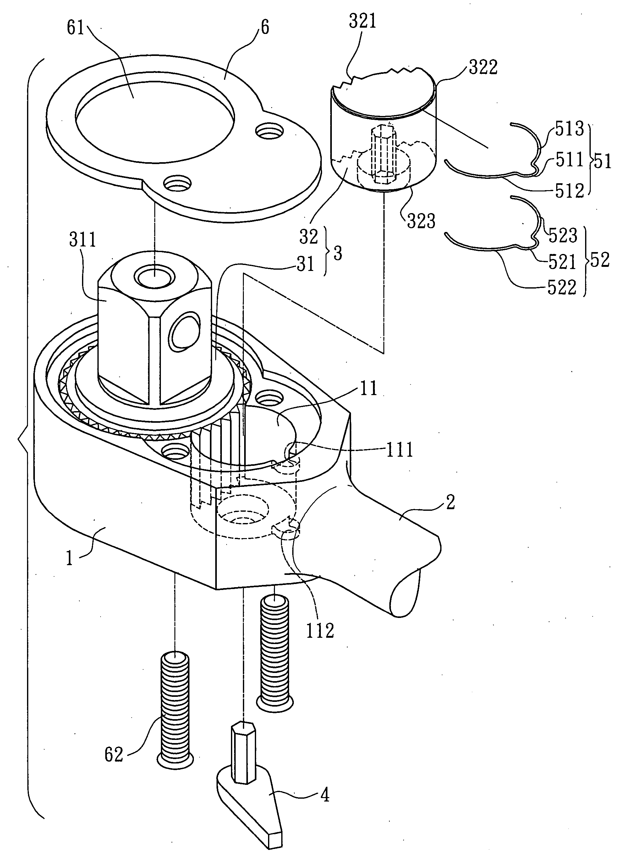
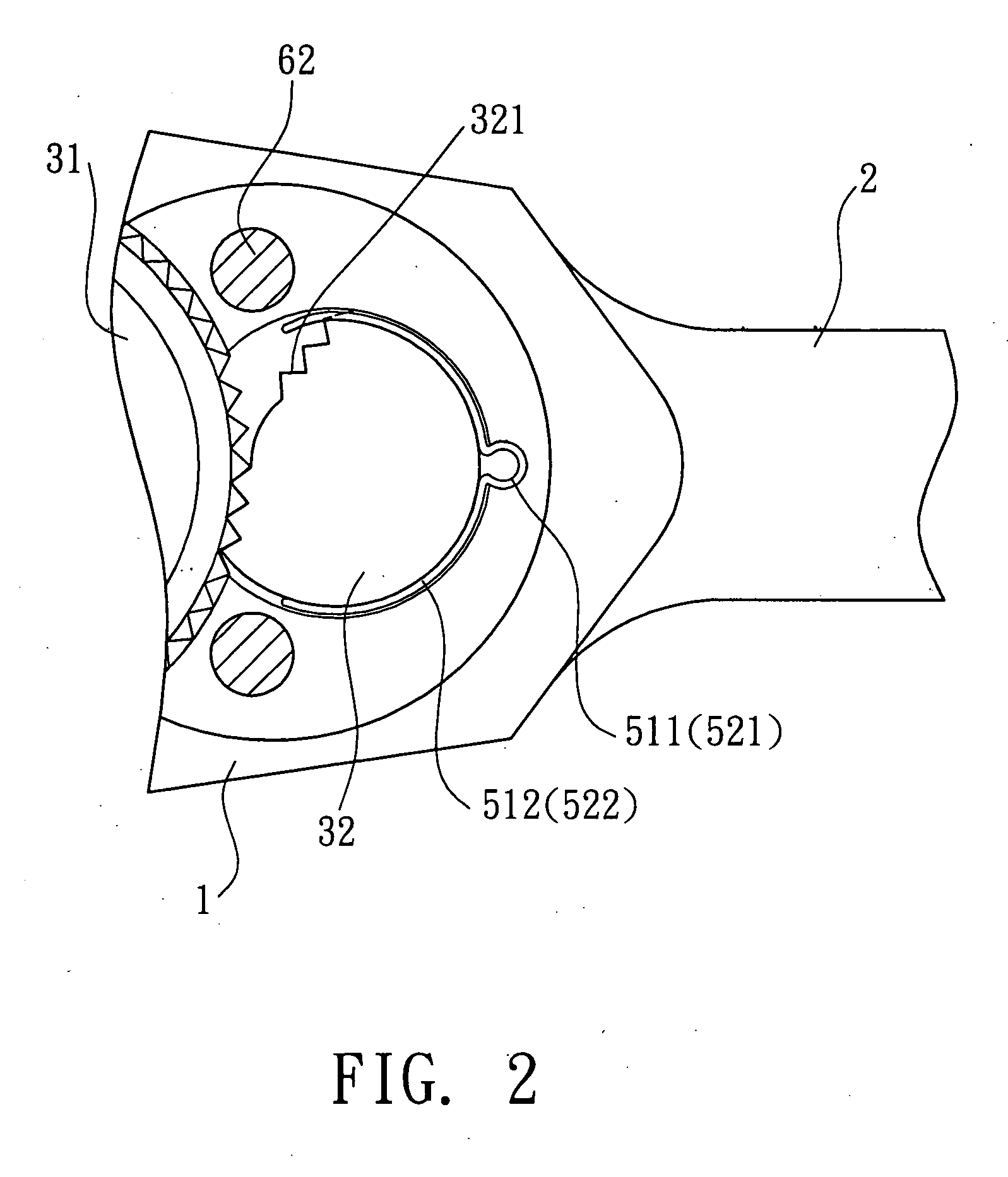
[0015] Referring to FIGS. 1 and 2, the ratchet tool of the present invention comprises a head 1 and a handle 2 connected to the head 1. A hole 11 is defined in the head 1 and a ratchet mechanism 3 is received in the hole 11. A first notch 111 and a second notch 112 are defined in an inner periphery of the hole 11.

[0016] The ratchet mechanism 3 includes a driving member 31 which includes teeth defined in an outer periphery thereof and a driving stub 311 extends from a side of the driving member 31. The driving stub 311 includes a rectangular cross section so as to be engaged with a socket or other parts. A pawl 32 is located beside the driving member 31 and includes a toothed surface 321 and a curved back which includes a first groove 322 and a second groove 323. A selection member 4 is pivotably connected to the head 1 and has a polygonal extension which is securely engaged with a polygonal recess defined in an underside of the pawl 32, such that the pawl 32 can be pivoted about an...


PUM


Abstract

A ratchet mechanism for a ratchet tool includes a driving member having teeth defined in an outer periphery thereof and a driving stub. A pawl is located beside the driving member and has a toothed surface for being engaged with the teeth of the driving member. A selection member is connected to the pawl. A substantially U-shaped first spring member and a substantially U-shaped second spring member are respectively connected to the head and the pawl is enclosed and clamped between the left biasing portions and the right biasing portions of the first and second spring members.

Description

FIELD OF THE INVENTION [0001] The present invention relates to a ratchet mechanism for ratchet tools and the mechanism includes biasing members for returning the pawl. BACKGROUND OF THE INVENTION [0002] A conventional ratchet tool 7 is shown in FIG. 8 and generally includes a driving member 71 rotatably received in a hole of the head of the tool 7 and the driving member 71 includes teeth 72 defined in an outer periphery thereof and a driving stub 73 extending from therefrom so that workpieces can be engaged with the driving stub 73. A ratchet mechanism is located beside the driving member 71 and includes a pawl unit 74 which includes two pawl member 75, 76. Two springs 77 are biased between the two pawl members 75, 76 and an inner periphery of the hole of the head. A cam 8 is rotatably located between the two pawl members 75, 76 such that when rotating the cam 8, one of the two pawl members 75, 76 can be pushed away from the driving member 71 and the other pawl member 76 is pushed b...

Claims


Application Information

Patent Timeline
Patent Type & Authority Applications(United States)
IPC IPC(8): B25B13/46
CPCB25B13/463
Inventor LEE, CHANG CHUAN
Owner LEE CHANG CHUAN
Features
  • R&D
  • Intellectual Property
  • Life Sciences
  • Materials
  • Tech Scout
  • Unparalleled Data Quality
  • Higher Quality Content
  • 60% Fewer Hallucinations
Learn More