Disc brake hub adapter structure

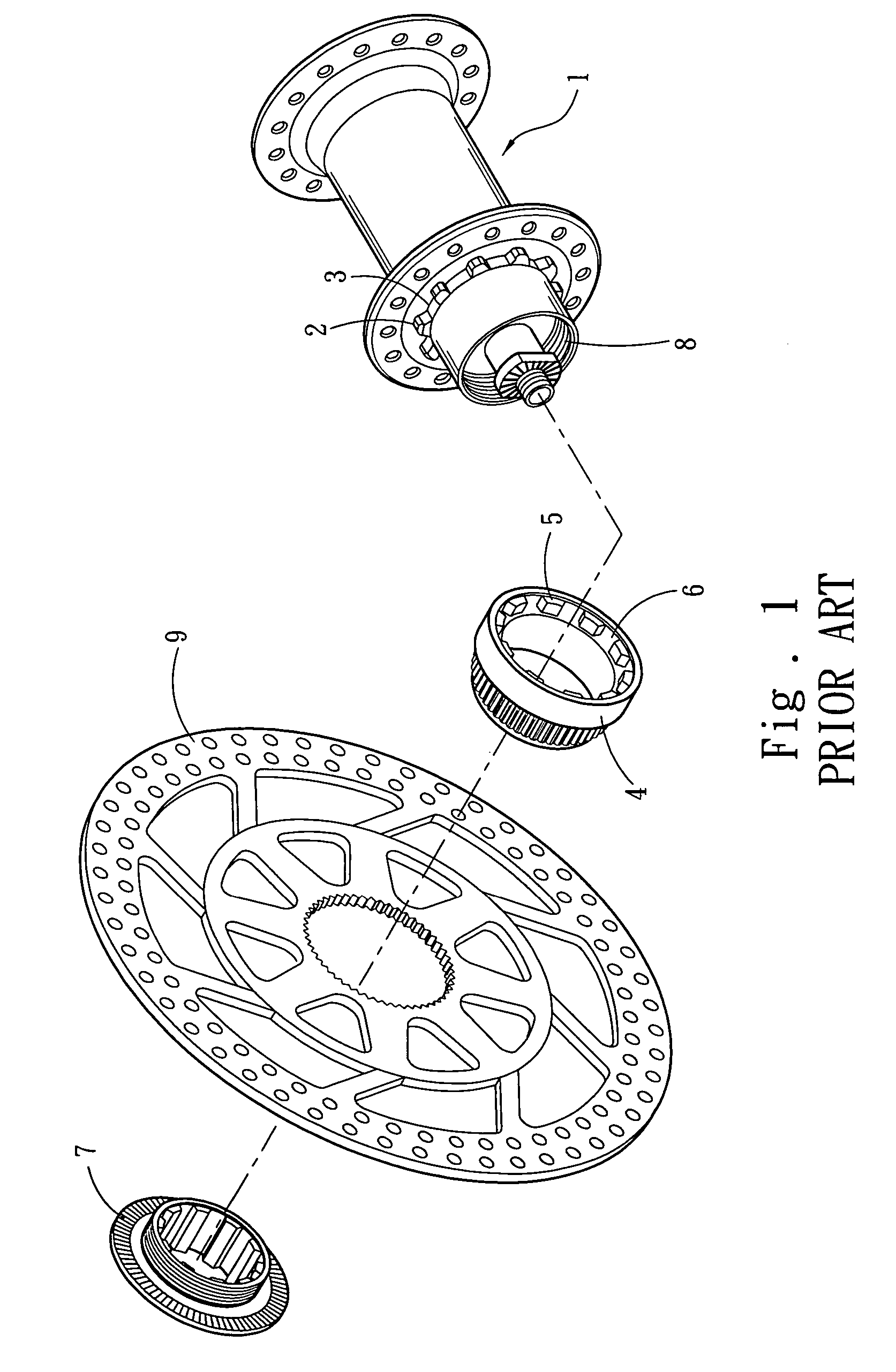
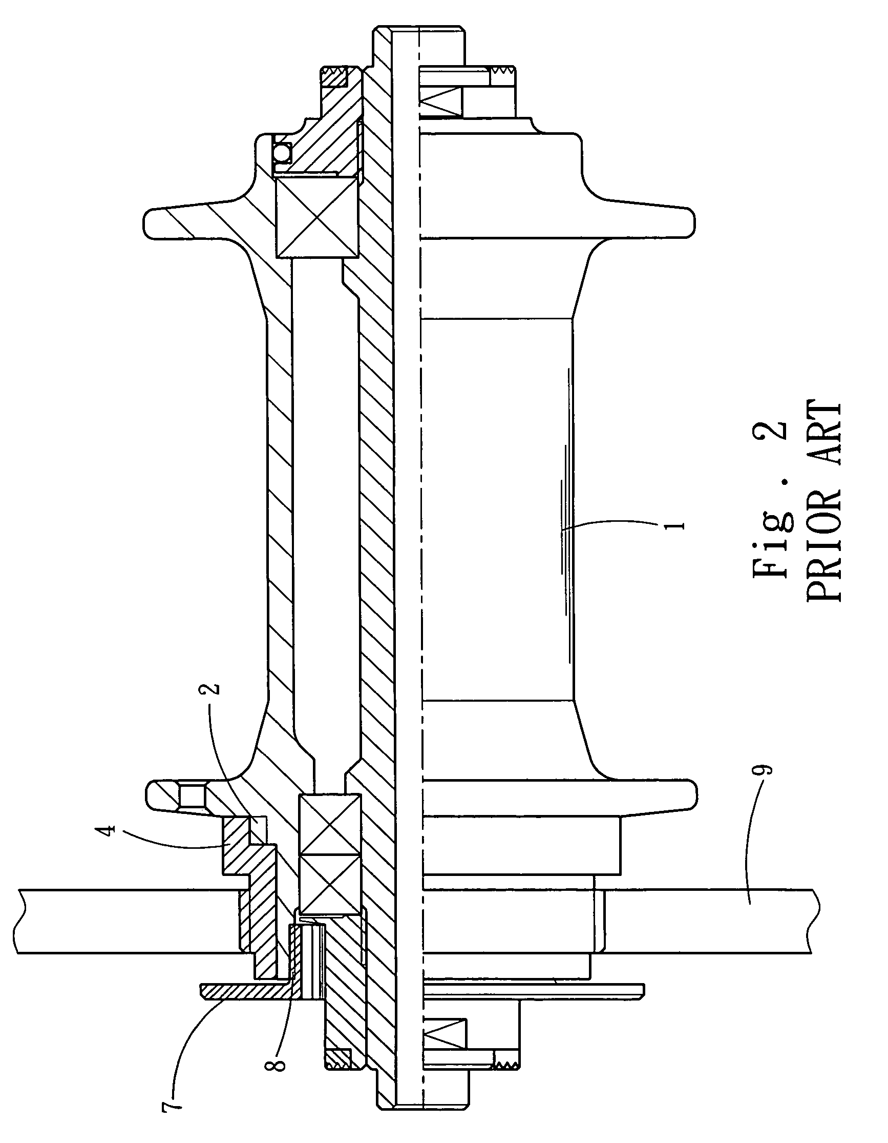
a technology of adapter and disc brake, which is applied in the direction of cycle brakes, braking elements, cycle equipment, etc., can solve the problem that the adapter b>4/b> of this type cannot be installed into the center hole of the plum blossom shaped brake disk

Inactive Publication Date: 2006-10-05
JOY IND
View PDF12 Cites 20 Cited by
  • Summary
  • Abstract
  • Description
  • Claims
  • Application Information

AI Technical Summary

Problems solved by technology

Furthermore, the adapter 4 of this sort cannot be installed into the center hole of a plum blossom shaped brake disk.

Method used


Image

  • Disc brake hub adapter structure
  • Disc brake hub adapter structure
  • Disc brake hub adapter structure

Examples


Embodiment Construction

[0008] To make it easier for our examiner to understand the objective of the invention, its structure, innovative features, and performance, we use a preferred embodiment and the attached drawings for the detailed description of the invention.

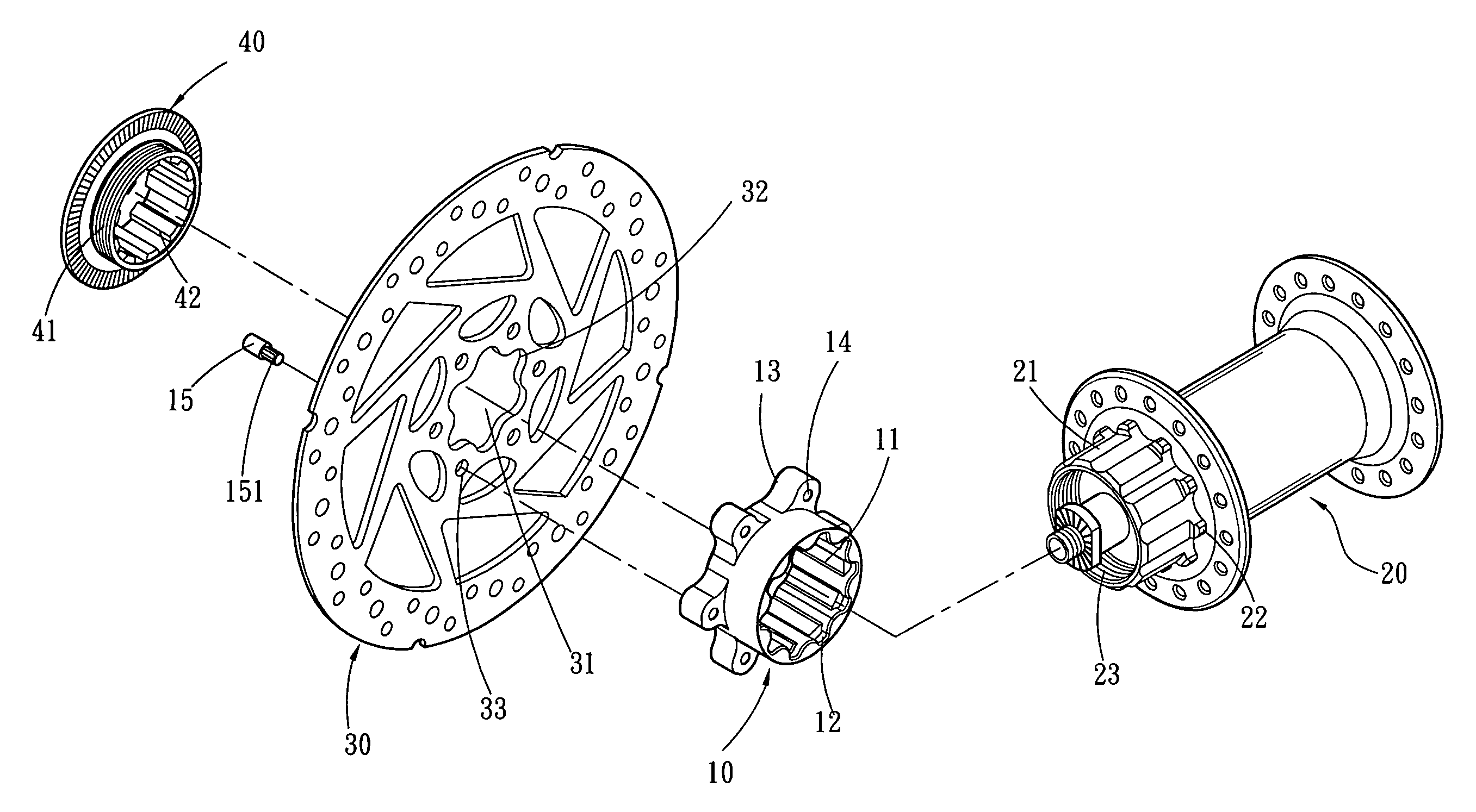
[0009] Referring to FIG. 3, a disc brake hub adapter structure in accordance with the present invention comprises: a hollow cylinder 10; a hub 20 coupled on its internal side; a brake disc 30 installed on its external side; a plum blossom shaped wavy thread disposed on a wall surface of an internal periphery of the cylinder 10 and engaged with the corresponding shape of an axle 21 of the hub 20; a plurality of concave teeth 12 disposed around the internal periphery of the cylinder 10 at a position proximate to a side of the hub 20 and coupled onto the embedding teeth 5 on the internal side of the axle 21 of the hub 20; a connecting section extended circularly from the external wall of the cylinder 10, and the connecting section is comprised of...


PUM


Abstract

The present invention discloses a disc brake hub adapter structure, which is a hollow cylinder having a plum blossom shaped wavy thread on its internal periphery to be engaged with an axle having a corresponding shape with the hub, and a plurality of embedding teeth disposed around the corner folding position is disposed at the internal side of the axle of the hub and engaged with a plurality of concave teeth around the internal side of the adapter, wherein the adapter has a connecting section extended outward from a side ring at the external periphery of the adapter. The connecting section has a plurality of holes for receiving a connecting device and connecting a brake disc with a plum blossom shaped center hole.

Description

FIELD OF THE INVENTION [0001] The present invention relates to an adapter of a bicycle hub that connects a brake disc and a hub, such that the special space configuration of the adapter can connect the hub with a center hole of a plum blossom shaped brake disc. BACKGROUND OF THE INVENTION [0002] Referring to FIGS. 1 and 2 for a prior art bicycle hub adapter structure, the adapter structure includes a hollow cylindrical hub 1, a plurality of latch teeth 2 around the corner folding position along a lateral wall of the hub 1 and the axial wall of the hub 1, a slot 3 formed between two latch teeth 2, a plurality of spokes for connecting the external periphery of the hub 1 with a tire (not shown in the figure), an adapter 4 passing sideway through the external side of the hub 1, a plurality of protruded embedding teeth 5 disposed around the internal side of the adapter 4, and a concave tooth 6 disposed between two embedding teeth 5, such that an opening at the internal side of the adapte...

Claims


Application Information

Patent Timeline
Patent Type & Authority Applications(United States)
IPC IPC(8): B62L5/00
CPCB62L1/005F16D2065/1392F16D2065/1356F16D65/12
Inventor CHEN, CHUN-HSUNG
Owner JOY IND
Why Eureka
Try Eureka