Display drive apparatus, display apparatus and drive control method thereof

a technology of display apparatus and drive control method, which is applied in the direction of instruments, computing, electric digital data processing, etc., can solve the problems of difficult to stably realize a light-emitting operation for a long period, and achieve favorable and uniform display image quality

Active Publication Date: 2006-10-05
SOLAS OLED LTD
View PDF23 Cites 128 Cited by
  • Summary
  • Abstract
  • Description
  • Claims
  • Application Information

AI Technical Summary

Benefits of technology

[0022] The present invention has advantages of compensating for change and variation in the element characteristics of the drive element and providing a favorable and uniform display image quality in a display drive apparatus and a display apparatus pr...

Problems solved by technology

As a result, it becomes difficult to stably realize a light emitting operation for...

Method used


Image

  • Display drive apparatus, display apparatus and drive control method thereof
  • Display drive apparatus, display apparatus and drive control method thereof
  • Display drive apparatus, display apparatus and drive control method thereof

Examples


first example

[0233]FIG. 17 is a timing chart illustratively showing a first example of the display drive method of the display apparatus according to the embodiment.

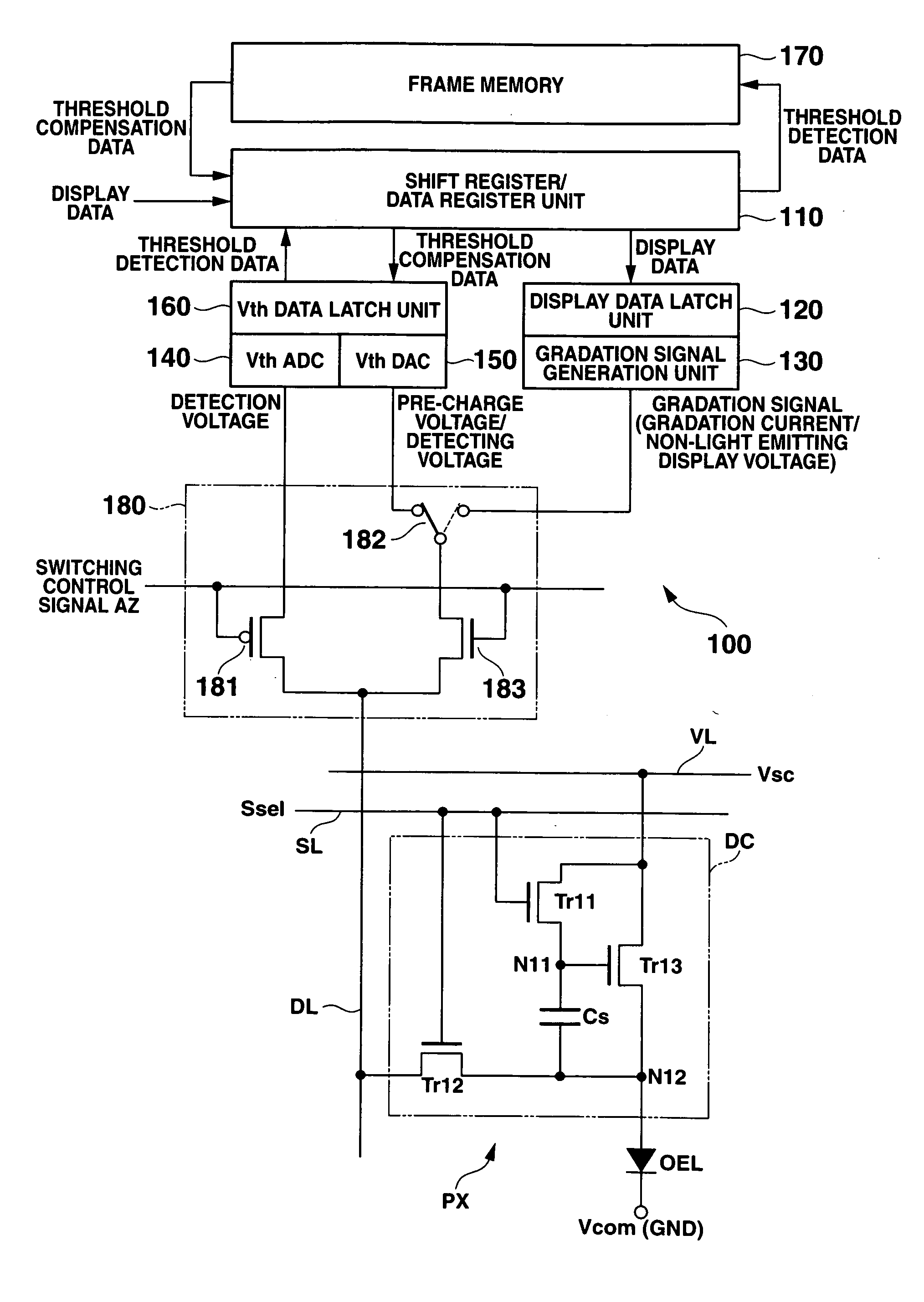
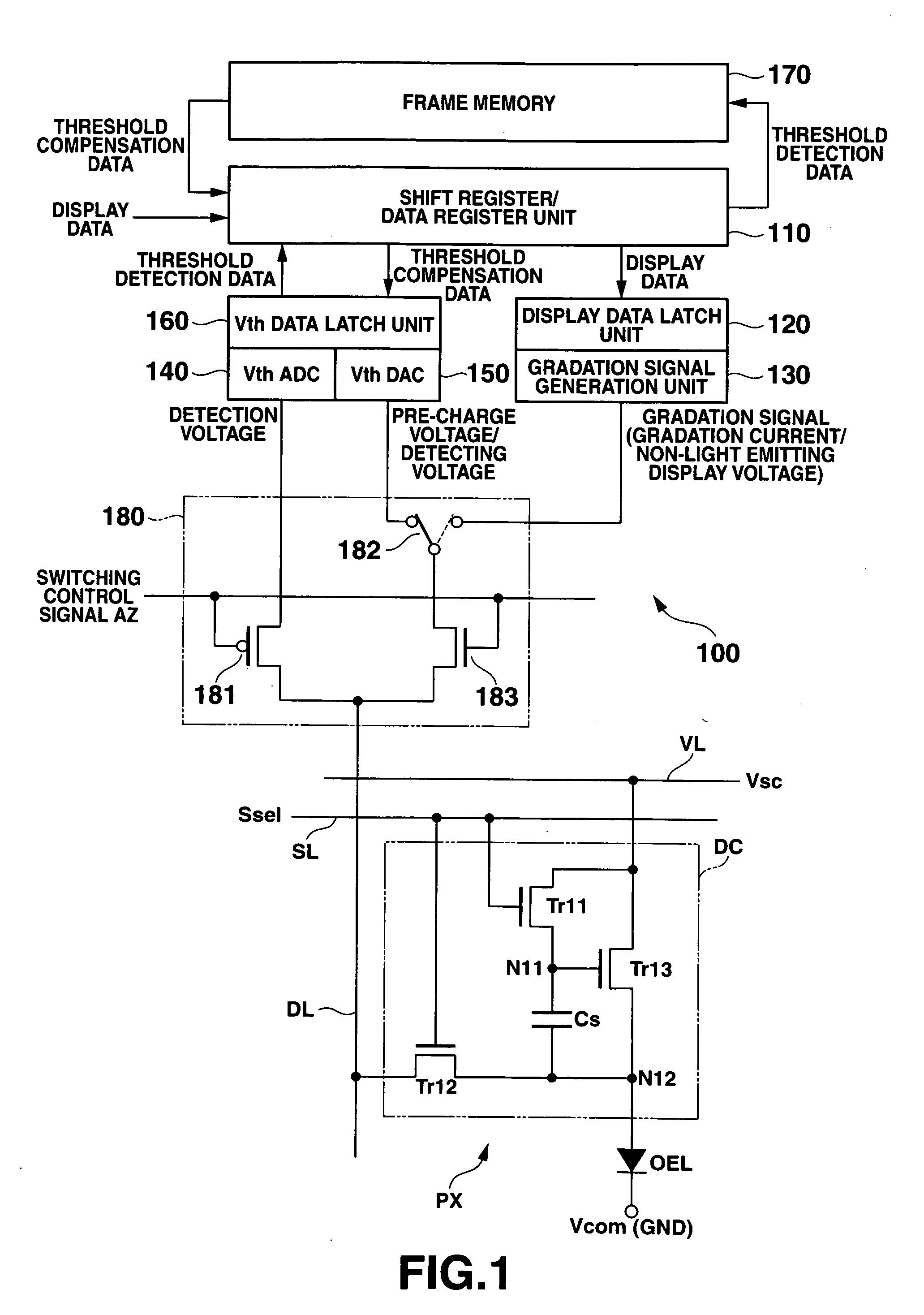
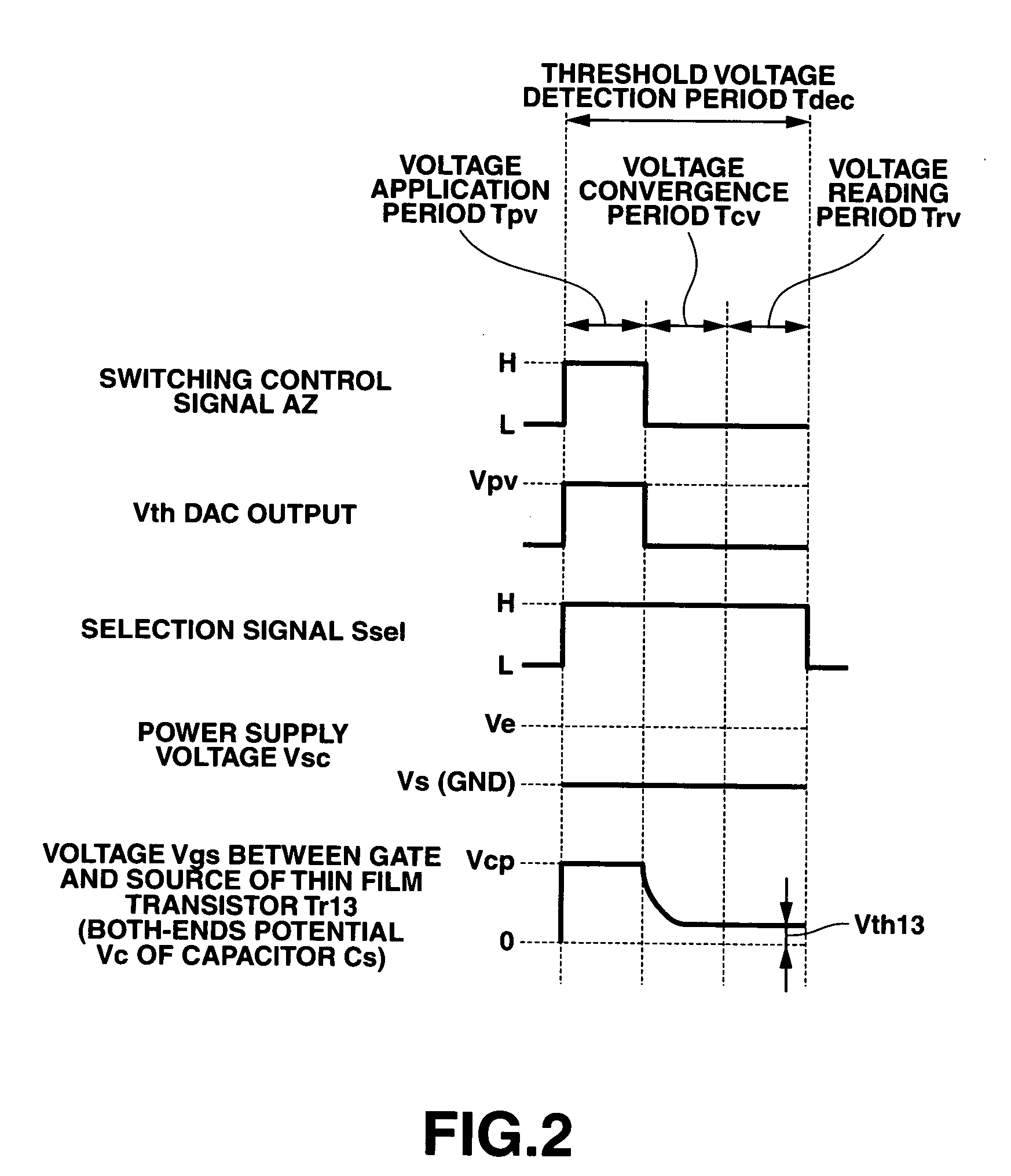
[0234] Here, an explanation will be omitted with respect to the drive control method (refer to FIGS. 2 and 7) which is the same as the case in the display drive apparatus and the display pixel (the drive circuit) shown in the above-described embodiment.

[0235] Incidentally, for the sake of explanation, the present embodiment has conveniently explained that a configuration is provided in which twelve rows (the first to twelfth rows) of display pixels are arranged. However, it goes without saying that the present invention is not limited thereto.

[0236] In the first example of the drive control operation of the display apparatus 200 according to the embodiment, generally, as shown in FIG. 17, a threshold voltage detection operation (a threshold voltage detection period Tdec) is first performed for detecting a threshold voltage (or a v...

second example

[0259] Next, by referring to the drawings, there will be explained a second example of the drive control method which is applicable to the display apparatus according to the embodiment.

[0260]FIG. 18 is a timing chart illustratively showing the second example of the drive control method of the display apparatus according to the embodiment.

[0261] Here, an explanation is simplified with respect to the drive control method which is the same as the first example (refer to FIG. 17) described above. In addition, the hatching portion in the figures shows the same operation state as the first example described above.

[0262] In addition, FIG. 19 is a structural diagram of a primary part showing one example of a display apparatus for realizing the second example of the drive control method of the display apparatus according to the embodiment.

[0263] Here, the same components as those of the display apparatus shown in the embodiment described above will be explained by attaching the same refe...

third example

[0274] Next, there will be explained a third example of the drive control method which is applicable to the display apparatus according to the embodiment with reference to the drawings.

[0275]FIG. 20 is a timing chart illustratively showing the third example of the display control method of the display apparatus according to the embodiment.

[0276] Here, an explanation on the drive control method same as that of the second example (refer to FIG. 18) described above will be simplified.

[0277] As shown in FIG. 20, the third example of the drive control method of the display apparatus 200 according to the embodiment is configured in the same manner as the second example described above, such that the threshold voltage detection operation is sequentially performed at a predetermined timing for each row with respect to all the display pixels PX arranged on the display panel 210 prior to the display drive operation followed by sequentially performing for each group for sequentially perform...


PUM


Abstract

There is provided a display drive apparatus for operating, in accordance with display data, a current control type optical elements each having a display pixel provided with the optical element and a drive element which supplies a driving current to the optical element. The display drive apparatus includes a gradation signal creating circuit which generates a gradation signal corresponding to a luminance gradation of the display data and supplies the gradation signal to the display pixel, a threshold voltage detection circuit which detects a threshold voltage peculiar to the drive element of the display pixel, and a compensation voltage application circuit which generates a compensation voltage for compensating for the threshold voltage of the drive element on the basis of the threshold voltage and applies the compensation voltage to the drive element.

Description

CROSS-REFERENCE TO RELATED APPLICATIONS [0001] This application is based upon and claims the benefit of priority from prior Japanese Patent Applications No. 2005-101905, filed Mar. 31, 2005; and No. 2005-105373, filed Mar. 31, 2005, the entire contents of both of which are incorporated herein by reference. BACKGROUND OF THE INVENTION [0002] 1. Field of the Invention [0003] The present invention relates to a display drive apparatus, a display apparatus provided with the display drive apparatus, and a drive control method thereof, and more particularly, to a display drive apparatus which is applicable to a display panel formed by arranging a plurality of current control type optical elements which are driven by being supplied with a current corresponding to display data, a display apparatus provided with the display drive apparatus, and a drive control method thereof. [0004] 2. Description of the Related Art [0005] In recent years, light weight and thin type display devices which cons...

Claims


Application Information

Patent Timeline
IPC IPC(8): G09G3/30
CPCG09G3/325G09G2300/0417G09G2300/0842G09G2300/0866G09G2310/0216G09G2320/043G09G2310/0251G09G2310/027G09G2320/0261G09G2320/029G09G2320/0295G09G2310/0227
Inventor SHIRASAKI, TOMOYUKIOGURA, JUN
Owner SOLAS OLED LTD
Why Eureka
Try Eureka