Multistage turbine with single blade row, and gas turbine using same

a multi-stage turbine and gas turbine technology, which is applied in the direction of machines/engines, stators, liquid fuel engines, etc., can solve the problems of reducing the performance of the blade, the flow passage area of the tip turbine also tends to be large, and the hub diameter of the tip turbine inevitably tends to be larger than the diameter of the fan, so as to improve the energy efficiency of the gas turbine and reduce the length of the axis of the gas turbine. , the structure of th

Inactive Publication Date: 2006-10-05
JAPAN AEROSPACE EXPLORATION AGENCY
View PDF1 Cites 0 Cited by
  • Summary
  • Abstract
  • Description
  • Claims
  • Application Information

AI Technical Summary

Benefits of technology

[0022] In the gas turbine described in claim 4, the multistage turbine with a single blade row described in claim 1 is used, thus supplied energy is desirably recovered by the multistage turbine with a single blade row, and energy efficiency of the gas turbine is improved. Moreover, a rotation axis for transmitting power to the fan or compressor is no longer required, thus the structure of the gas turbine is simplified, such that the length of the axis of the gas turbine is reduced and the weight of same is also reduced.
[0023] According to the multistage turbine with a single blade row, the first corresponding blade and the second corresponding blade configuring the second stationary blade row are disposed in relation to the first reference blade and the second reference blade of a first stationary blade row 2 respectively. Particularly, in a section in which a rotor blade is exposed to the high-pressure working fluid from the low-pressure working fluid, the first corresponding blade is disposed so that pressure gradient on the suction side of the rotor blade and on the pressure side of same are minimized as much as possible when the rotor blade makes the closest approach to an upper end of the first corresponding blade. In a section in which the rotor blade is exposed to the low-pressure working fluid from the hi

Problems solved by technology

On the other hand, the hub diameter of the tip turbine inevitably tends to become larger than the diameter of the fan, and the flow passage area of the tip turbine also tends to become large.
However, a radical reduction of the height of the rotor blade causes degradation of performance of the blade, thus conformity of the amount of the working fluid flowing inside the turbine with the flow passage area of the turbine cannot be achieved, a partial turbine or the like in which a tip turbine is disposed in a part of the circumference of fan is used.
Especially when the tip turbine comprises only a single rotor blade row, desired circumferential speed cannot be obtained, and a heat drop required for the tip turbine to drive the fan cannot be absorbed.
However, when a working fluid of high pressure and a working fluid of low pressure flow parallel to each other, a large quantity of the high-pressure working f

Method used


Image

  • Multistage turbine with single blade row, and gas turbine using same
  • Multistage turbine with single blade row, and gas turbine using same
  • Multistage turbine with single blade row, and gas turbine using same

Examples


Embodiment Construction

[0030] Hereinafter, the present invention is described in detail using the embodiments shown in the figures.

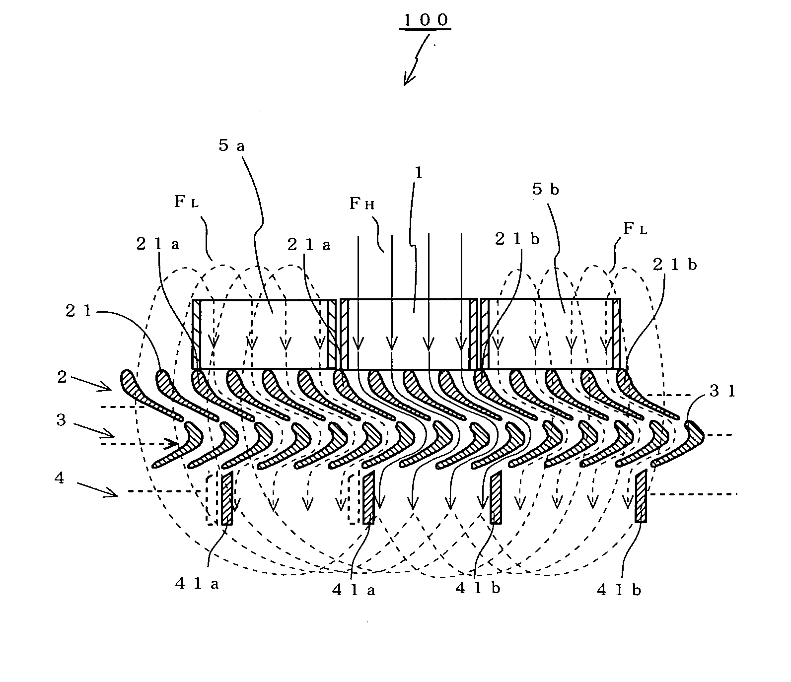
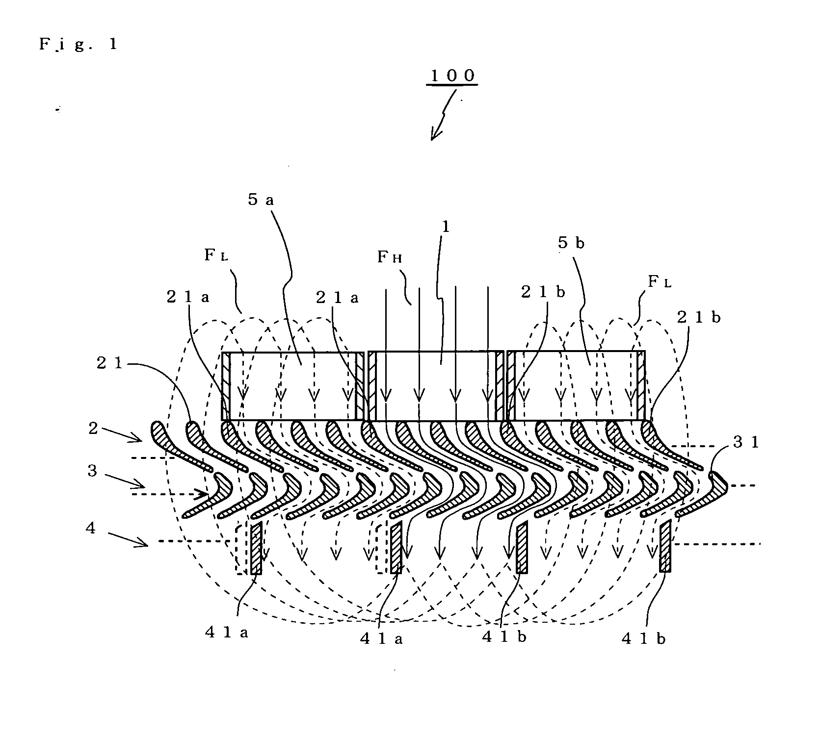
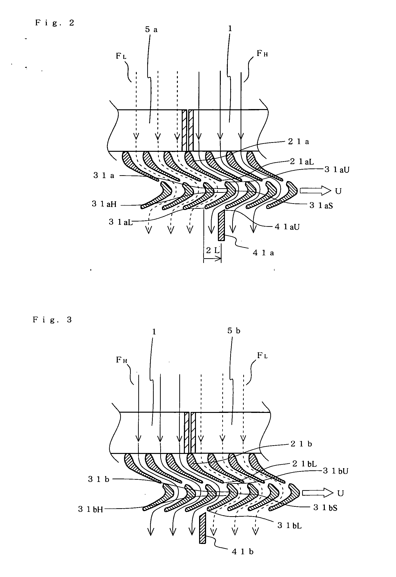
[0031]FIG. 1 is a cross-section diagram of a substantial part, which shows an embodiment of the multistage turbine with a single blade row according to the present invention. This cross-section diagram of a substantial part is to show a substantial part of the multistage turbine with a single blade row of the present invention in the form of a two-dimensional development, the substantial part being obtained by cutting the multistage turbine with a single blade row at its cylindrical surface.

[0032] This multistage turbine with a single blade row 100 comprises a high-pressure side suction duct 1 into which a high-pressure working fluid FH flows, a first stationary blade row 2 which functions as a nozzle for increasing the speed of working fluids, a rotor blade row 3 in which the working fluids pass through between the blades while being subjected to adiabatic expansion, a seco...


PUM


Abstract

In order to desirably prevent leakage of a working fluid from the tip clearance to reduce loss of a heat drop of the working fluid, a first corresponding blade of a second stationary blade row, which corresponds to a first reference blade of a first stationary blade row, is disposed in a position distant by 2L from the position of a lower end of a rotor blade in the direction of movement of the rotor blades when the rotor blade makes the closest approach to a lower end of the first reference blade. It should be noted that L is a value obtained by multiplying the average time T required for the high-pressure working fluid to pass through the rotor blade by the traveling speed U of the rotor blade. On the other hand, a second corresponding blade of the second stationary blade row, which corresponds to a second reference blade of the first stationary blade row, is disposed in a position of a lower end of a rotor blade when the rotor blade makes the closest approach to a lower end of the first reference blade.

Description

BACKGROUND OF THE INVENTION [0001] 1. Field of the Invention [0002] The present invention relates to a multistage turbine with a single blade row and a gas turbine, and more particularly to a high-efficiency multistage turbine with a single blade row for desirably preventing leakage of a working fluid from the tip clearance to reduce loss of a heat drop of the working fluid, and a gas turbine using the multistage turbine with a single blade row. [0003] 2. Description of the Related Art [0004] The driving mechanism of fans in a general turbine engine is a low pressure turbine which is connected to the rotation axis of a fan. However, as another fan driving method, there is a tip turbine system in which a small turbine rotor blade (referred to as “tip turbine” hereafter) is embedded in a leading end of a fan. In this tip turbine system, a tip turbine is embedded in a circumferential end portion of a fan, thus there are advantages that a rotation axis for connecting a low pressure turb...

Claims


Application Information

Patent Timeline
IPC IPC(8): F01D1/12
CPCF01D1/12F01D5/142F05D2240/12Y02T50/673F02C3/073Y02T50/60
Inventor IWASE, SHIKISAITO, YOSHIO
Owner JAPAN AEROSPACE EXPLORATION AGENCY
Why Eureka
Try Eureka