Mechanical chain tensioner with ratcheting device

a ratcheting device and chain tensioner technology, applied in the field of ratcheting devices in the field of tensioners, can solve the problems of insufficient means of adding a ratcheting device to the blade tensioner in the prior ar

Inactive Publication Date: 2006-10-19
BORGWARNER INC
View PDF19 Cites 19 Cited by
  • Summary
  • Abstract
  • Description
  • Claims
  • Application Information

AI Technical Summary

Benefits of technology

[0012] When the slack of the chain increases, the distal end of the blade shoe pivots away from the chain and slides on the first side of the sliding surface, forcing the ratchet rod toward the pivot pin. The toothed ramp of the ratchet rod is in contact with the edge of the spring clip and drags the spring clip on the second side of the sliding surface of the bracket along, until the spring clip tab mates with a corresponding indentation in the bracket. The slack of the chain may allow continued movement of the distal end of the blade shoe, ratcheting other teeth on the ratchet rod over the engaged edge of the spring clip.

Problems solved by technology

The prior art does not show an adequate means of adding a ratchet device to a blade tensioner.

Method used


Image

  • Mechanical chain tensioner with ratcheting device
  • Mechanical chain tensioner with ratcheting device
  • Mechanical chain tensioner with ratcheting device

Examples


Embodiment Construction

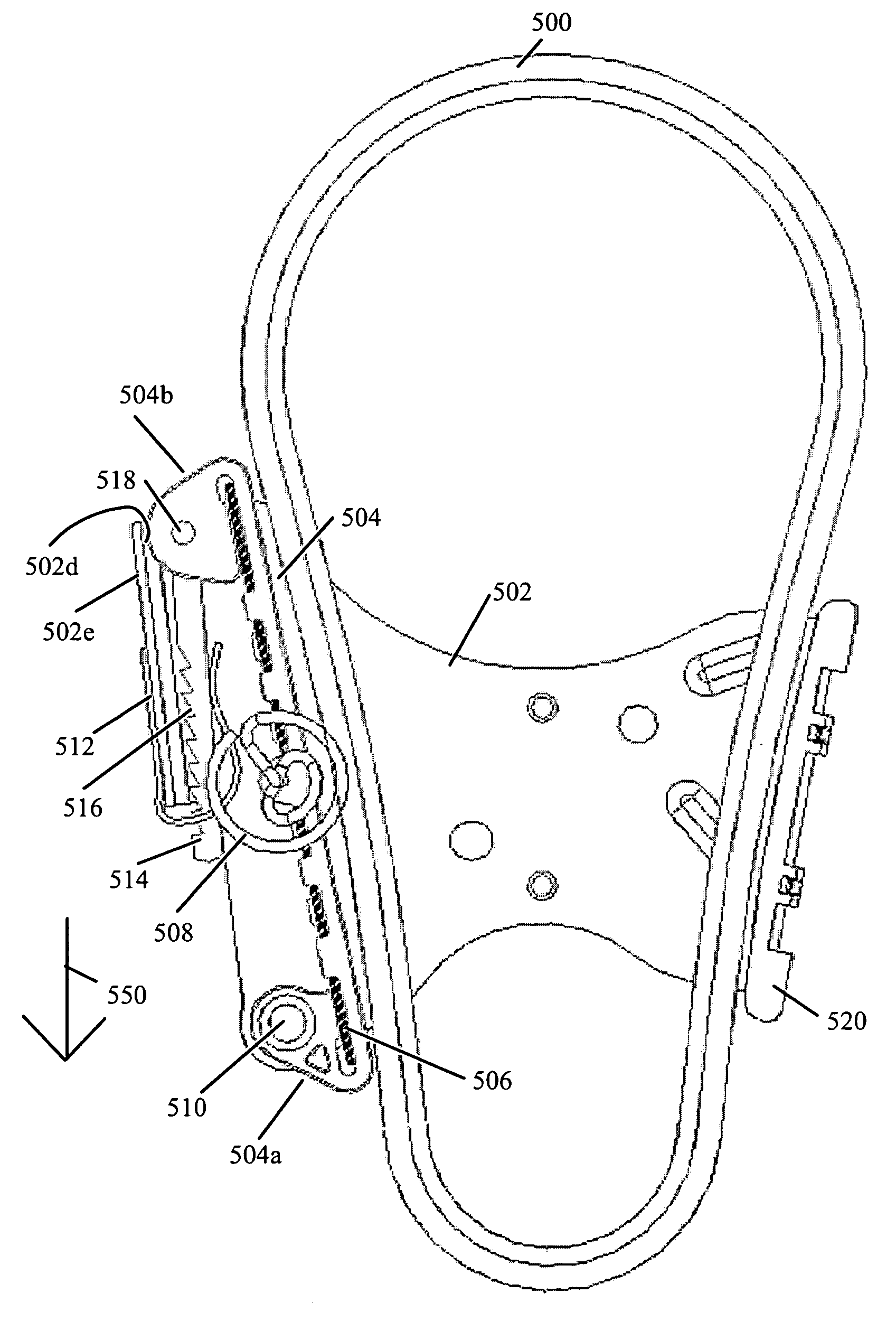
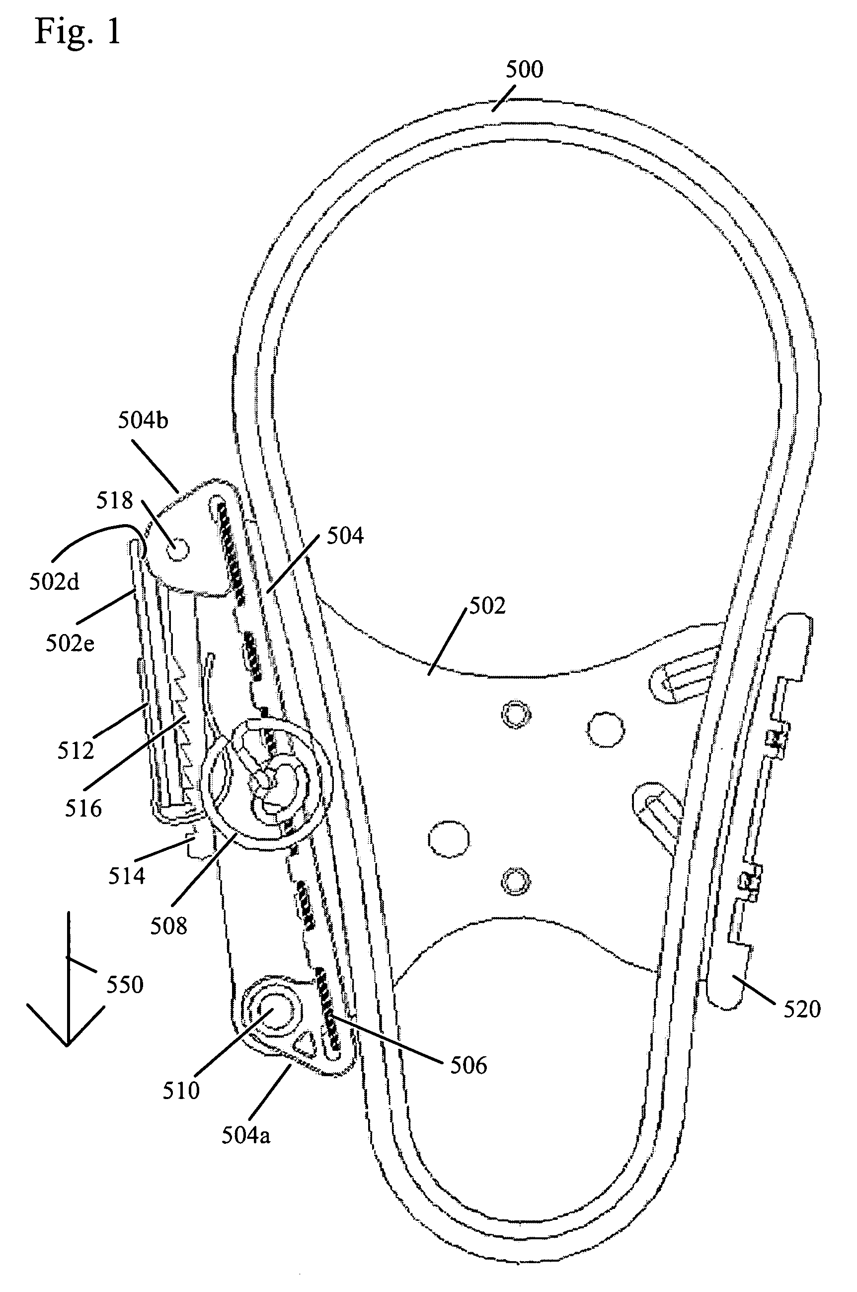
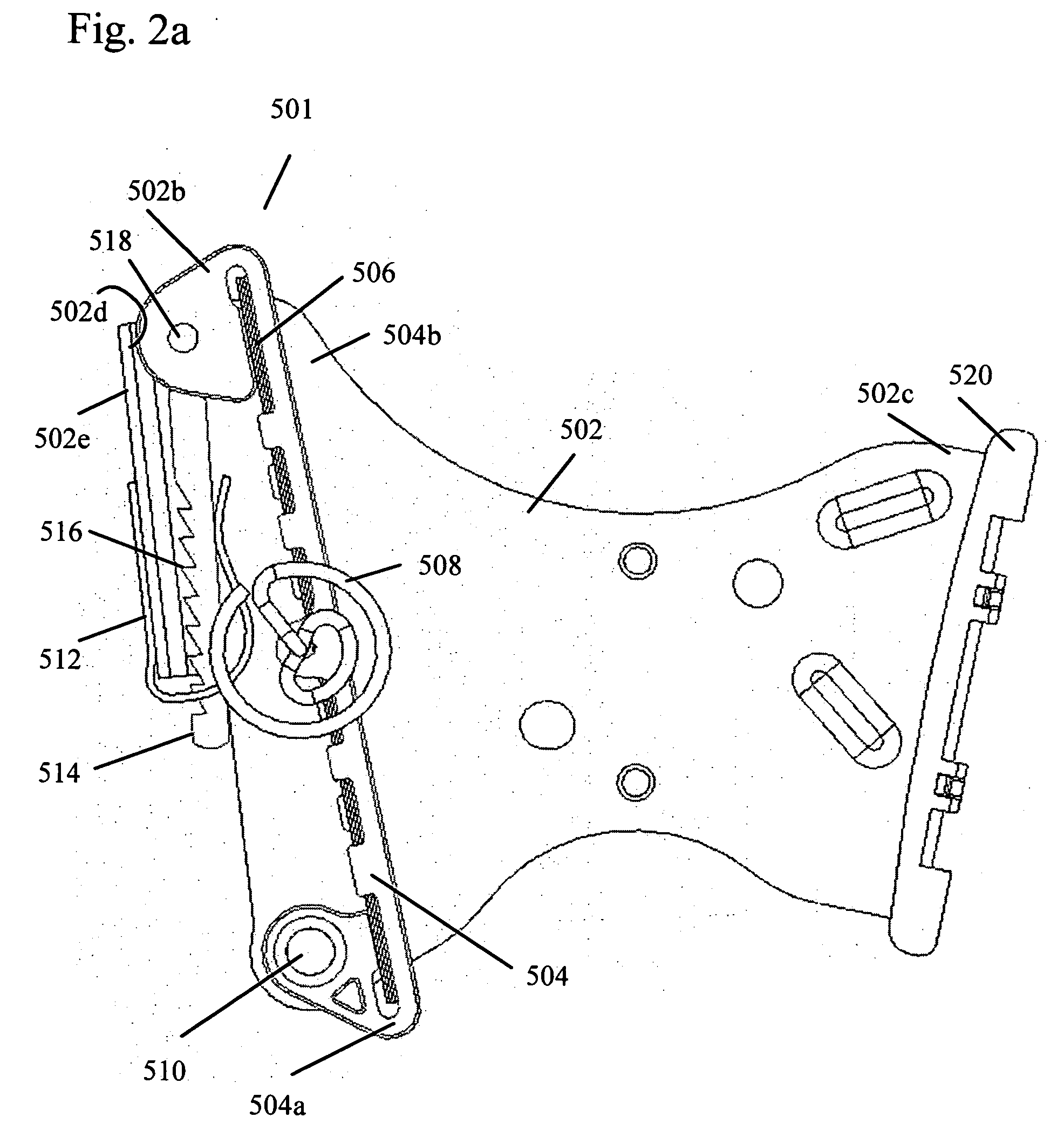
[0027]FIG. 1 shows a schematic of the tensioner 501 with a chain 500. FIGS. 2a and 2b show the tensioner 501 and bracket 502 without the chain. FIG. 3 shows just the bracket 502.

[0028] The tensioner 501 and guide 520 are attached to the bracket 502. Referring to FIGS. 2a and 2b, the tensioner is comprised of a blade shoe 504 having an arcuately curved chain sliding face 504c, a distal end 504b, and a proximal end 504a. The distal end 504b of the tensioner is bifurcated as shown in FIG. 5 and receives a first end 514a of ratchet rod 514 and pin 518. The proximal end of the blade shoe pivots on pivot pin 510 of bracket 502. A blade spring 506 is placed between the blade shoe 504 and the bracket 502. The blade spring 506 runs along the length of the blade shoe (e.g. from the distal end to the proximal end). The blade spring 506 may consist of a single blade spring or multiple blade springs.

[0029] Referring to FIG. 3, the bracket 502 has a guide side 502c and an opposing tensioner sid...


PUM


Abstract

A blade tensioner comprising a blade shoe, a sliding surface with a first and a second side, a ratchet rod attached to the distal end of the blade shoe having a length of teeth, and a spring clip for receiving the ratchet rod and being slidable along the second side of the sliding surface. The spring clip also has an edge for abutting the plurality of teeth of the ratchet rod. When the slack on the chain increases, a distal end of the blade shoe pivots and slides on the first side of the sliding surface, and the spring clip slides on the second side of the sliding surface a distance limited by the engagement of the tab of the spring clip with the corresponding indentation on the second side of the sliding surface and the edge of the spring clip abuts the teeth of the ratchet rod.

Description

BACKGROUND OF THE INVENTION [0001] 1. Field of the Invention [0002] The invention pertains to the field of tensioners. More particularly, the invention pertains to a tensioner with a ratcheting device. [0003] 2. Description of the Related Art [0004] Blade tensioners are commonly used to control a chain or belt where load fluctuations are not so severe as to over flex the spring or springs. A ratchet with backlash is added to tensioners to limit the effective backward or untensioned travel of a tensioning device. [0005] Prior art FIG. 12 shows an example of a blade tensioner. The conventional blade tensioner 410 includes a blade shoe 411 made of resin having a curved chain sliding face and numerous blade springs 421, preferably made of metallic material. The blade springs 421 are arranged in layers on the opposite side of the blade shoe 411 from the chain sliding face, and provide spring force to the blade shoe 411. The ends of each spring-shaped blade spring 421 are inserted in the ...

Claims


Application Information

Patent Timeline
Patent Type & Authority Applications(United States)
IPC IPC(8): F16H7/08F16H7/18
CPCF16H7/0848F16H2007/0878F16H2007/0853F16H2007/0804
Inventor MARKLEY, GEORGE L.CAPP, JAMES
Owner BORGWARNER INC
Why Eureka
Try Eureka